

Composition for forming a liquid crystal alignment film, and liquid crystal display device
a liquid crystal alignment and liquid crystal technology, applied in the direction of plastic/resin/waxes insulators, instruments, transportation and packaging, etc., can solve the problems of significant lowering of the display quality of the display panel, uneven display, poor coating properties of inkjet printing
- Summary
- Abstract
- Description
- Claims
- Application Information
AI Technical Summary
Benefits of technology
Problems solved by technology
Method used
Image

Examples
embodiment 1
[0118]The present Embodiment is mentioned in the following order: 1. alignment film material (material, for forming a liquid crystal alignment film); 2. preparation method of alignment film; 3. composition for forming a liquid crystal alignment film; and 4. basic operations of liquid crystal display device.
1. Alignment Film Material
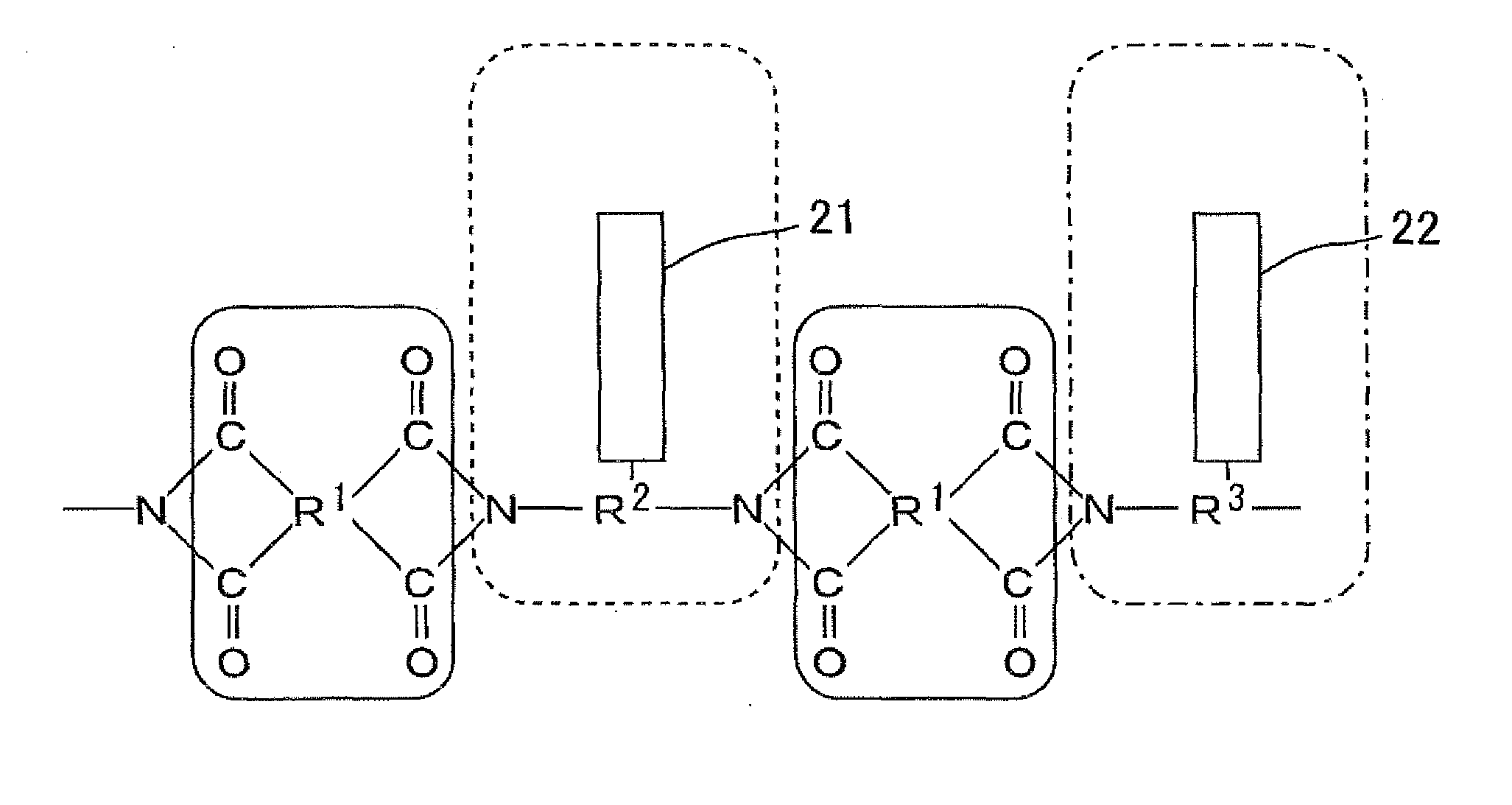
[0119]The alignment film material (material for forming a liquid crystal alignment film) of the present Embodiment includes a polymer (copolymer) essentially including a first constitutional unit and a second constitutional unit. The first constitutional unit starts exhibiting a property of controlling alignment of liquid crystal molecules by photoirradiation. The second constitutional unit exhibits a property of controlling alignment of liquid crystal molecules regardless of photoirradiation. More particularly, the first constitutional unit has a side chain including a photofunctional group, and the second constitutional unit has a side chain including a...
example 1
[0196]The ink was used whose solvent system was NMP / DEDG / DIBK=30 / 50 / 20. In addition, the ink was set to have a solid content of 2.8% by weight, a surface tension of 31 mN / m at 24° C., a viscosity of 4 mPa·s at 24° C., and to show the liquid spreading of 15 mm in a liquid spreading test and the liquid shrinkage of 100 nm in a liquid shrinkage test. In inkjet printing equipment used here, the nozzle pitch of heads was 0.75 mm, the number of nozzles was 64, and its stage velocity was set to 400 mm / sec. A substrate used here was a TFT substrate and a CF substrate, each of which had the contact angle with water of 0° to 3° and was preliminary washed by a normal cleaning method.
[0197]After carrying out inkjet printing to the TFT substrate and the CF substrate, prebaking at 80° C. for a minute and post baking at 200° C. for 40 minutes were sequentially carried out with a hot plate. Next, after a sealing material was applied to a predetermined position on the CF substrate with use of a disp...
example 2
[0198]A liquid crystal display panel of the Example 2 was produced in the same manner as in Example 1 except that the ink used here had, a solvent system of BL / NMP / DEDG / DIBK / DPE=20 / 30 / 39 / 10 / 1. In addition, the ink was set to have a solid content of 2.8% by weight, a surface tension of 29 mN / mn at 24° C., a viscosity of 4 mPa·s at 24° C., and to show a liquid spreading of 22 mm in a liquid spreading test and the liquid shrinkage of 100 nm in a liquid shrinkage test.
PUM
| Property | Measurement | Unit |
|---|---|---|
| surface tension | aaaaa | aaaaa |
| viscosity | aaaaa | aaaaa |
| boiling point | aaaaa | aaaaa |
Abstract
Description
Claims
Application Information