Mass production of pristine nano graphene materials

a nano graphene and mass production technology, applied in the field of nano graphene, can solve the problems of high cost of moderately priced multi-walled cnt, inability to use high-volume polymer composites and other functional or structural applications, and inability to meet the requirements of large-scale production, and achieve high production yield and low surface tension

Active Publication Date: 2011-01-27
GLOBAL GRAPHENE GRP INC
View PDF11 Cites 102 Cited by
  • Summary
  • Abstract
  • Description
  • Claims
  • Application Information

AI Technical Summary

Benefits of technology

[0025]The present invention provides a method of exfoliating a graphitic material to produce nano-scaled graphene platelets having a thickness smaller than 100 nm, typically smaller than 10 nm, and most typically smaller than 1 nm. The method comprises (a) dispersing particles of a graphitic material in a liquid medium containing no surfactant to obtain a suspension wherein the liquid medium has a low surface tension, characterized as having a contact angle on the graphene plane smaller than 90° (preferably <75°, more preferably <60°, further preferably <45°, and most preferably <30°); and (b) exposing the suspension to ultrasonic waves (a process commonly referred to as ultrasonication) at an energy or power level for a sufficient length of time to produce the separated nano-scaled platelets. This contact angle is measured on the graphene plane, not on the graphene edge surface. The suspension typically has a graphitic material content much greater than 0.1 mg / mL, more typically >1 mg / mL, most typically >10 mg / mL (hence, affording a truly high production yield). The power level is typically above 80 watts, but more typically above 150 watts and, in many cases, above 200 watts.

Problems solved by technology

However, attempts to produce CNT in large quantities have been fraught with overwhelming challenges due to poor yield and costly fabrication and purification processes.
Hence, even the moderately priced multi-walled CNTs remain too expensive to be used in high volume polymer composite and other functional or structural applications.
Further, for many applications, processing of nanocomposites with high CNT concentrations has been difficult due to the high melt viscosity.
However, this very difference in geometry also makes electronic structure and related physical and chemical properties very different between NGP and CNT.
There is a misconception in the scientific community that van der Waals forces are weak forces, which needs some qualifications.
However, the magnitude of van der Waals forces drops precipitously when the separation increases just slightly.
Unfortunately, typically a significant portion of the gaseous molecules escape without contributing to exfoliation of graphite flakes.
Additionally, many of the exfoliated flakes re-stack together by re-forming van der Waals forces if they could not be properly separated in time.
It is important to note that the separation treatment (e.g. using ultrasonication or shearing) is to separate those thick flakes from one another (breaking up the graphite worm or sever those weak interconnections), and it is not intended for further peeling off individual graphene planes.
In certain applications, the surfactant removal procedure could be challenging, tedious, or expensive, particularly where the NGP-liquid suspension is intended for use directly as a product (e.g., as a conductive ink, coating, or paint) and the presence of a surfactant is undesirable.
The presently invented process is fast and environmentally benign.
NMP is a highly polar solvent, and not ideal in cases where reaction chemistry requires a nonpolar medium.
Further, it is hygroscopic, making its use problematic when water must be excluded from reaction mixtures.

Method used


Image

  • Mass production of pristine nano graphene materials
  • Mass production of pristine nano graphene materials
  • Mass production of pristine nano graphene materials

Examples


example 1

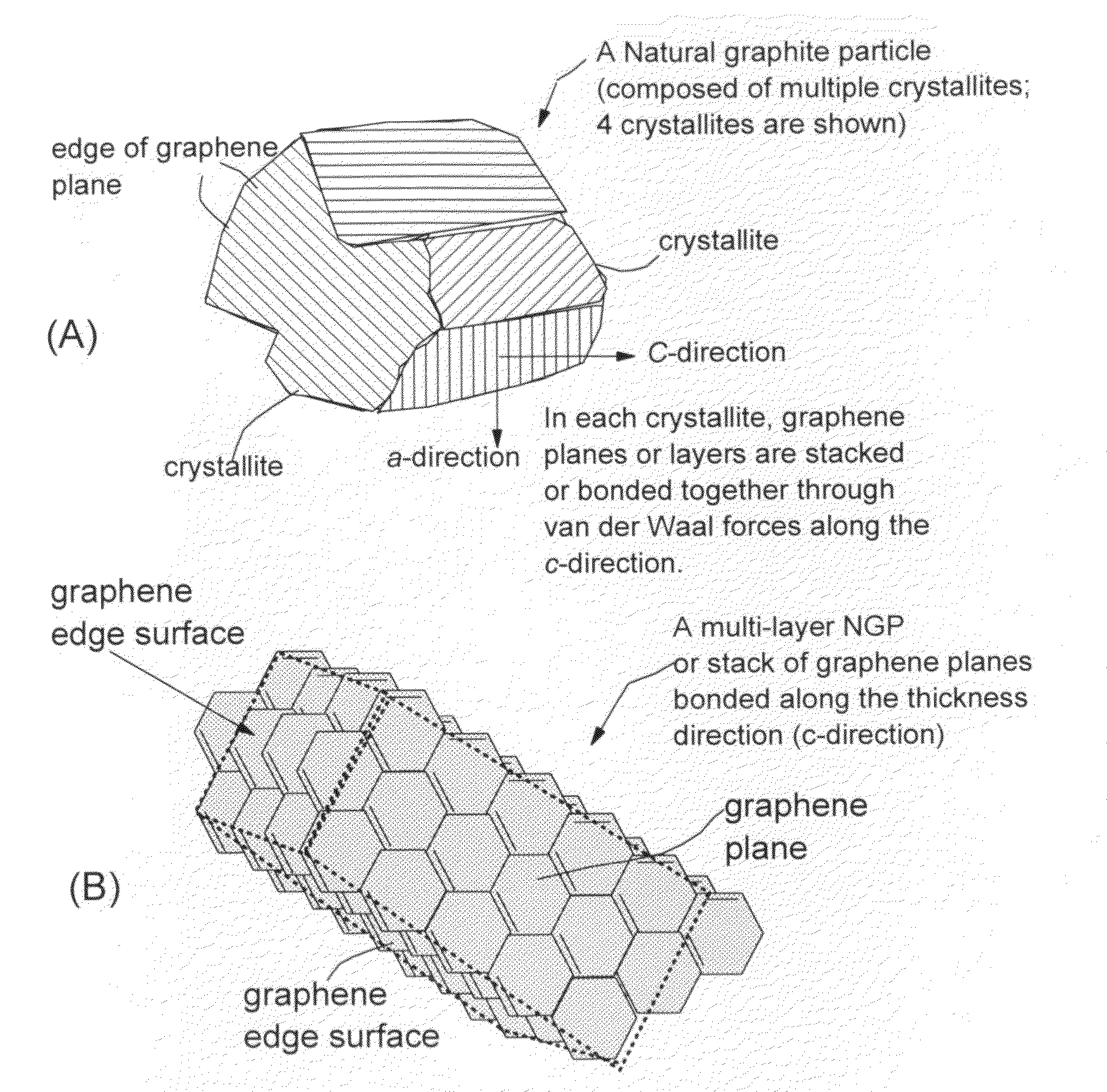
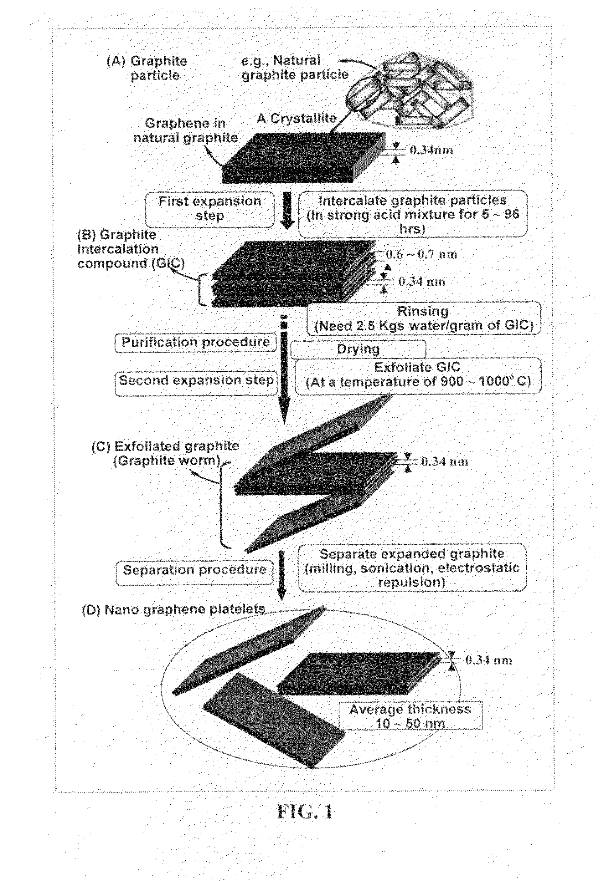
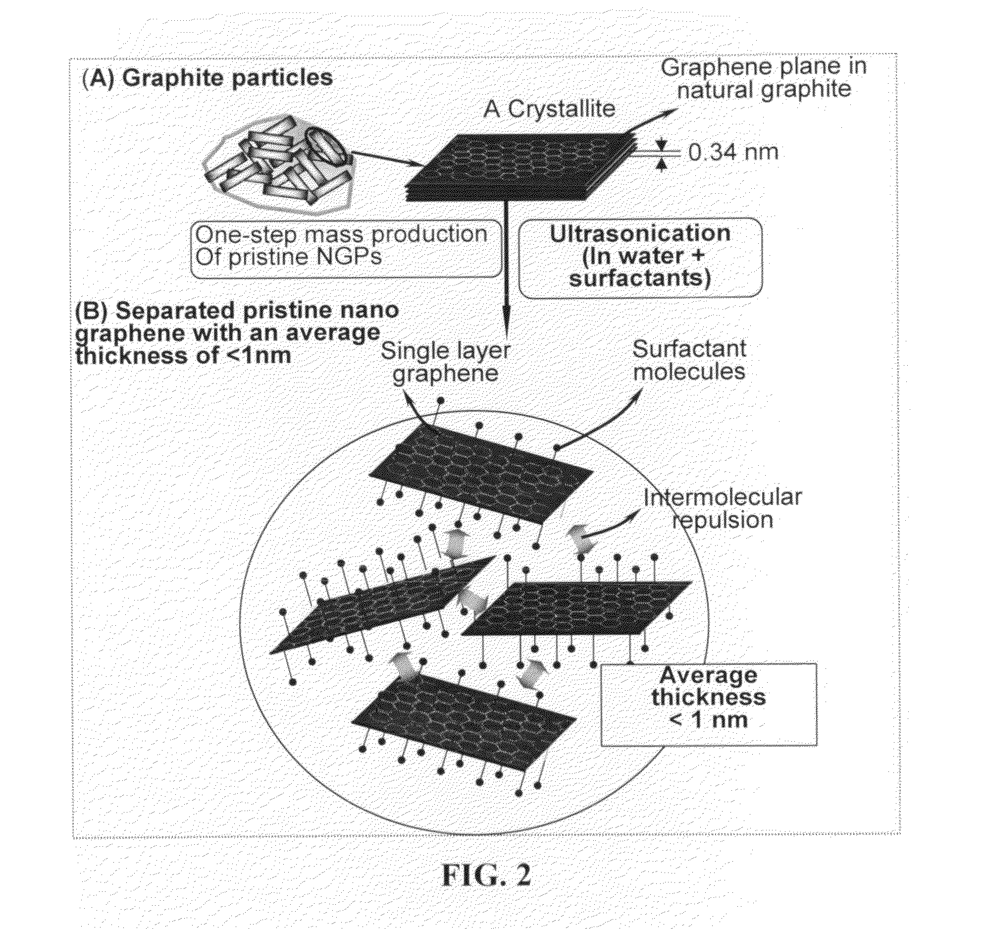
Nano-Scaled Graphene Platelets (NGPs) from Natural Graphite

[0073]Five grams of natural graphite, ground to approximately 20 μm or less in sizes, were dispersed in 1,000 mL of n-Heptane. An ultrasonic energy level of 200 W (Branson S450 Ultrasonicator) was used for exfoliation and separation of graphene planes for a period of ½ hours. The average thickness of the resulting NGPs was 2.1 nm.

example 2

Ultrasonication of Natural Graphite Using a Solvent of High Surface Tension

[0074]Five grams of natural graphite, ground to approximately 20 μm or less in sizes, were dispersed in 1,000 mL of glycerol (surface tension=63 mN / m and graphene surface contact angle=125 degrees) to obtain a suspension. An ultrasonic energy level of 150 W (Branson S450 Ultrasonicator) was used for a period of 1 hour. Graphite particles were broken down to approximately 300 nm in thickness. Very few NGPs were recovered from the suspension after one hour.

example 3

NGPs from MCMBs

[0075]Five grams of MCMBs (supplied from Shanghai Shan Shan Tech Co.) with an average particle size of approximately 18 μm, were dispersed in 1,000 mL of benzene. An ultrasonic energy level of 250 W (Branson S450 Ultrasonicator) was used for the exfoliation and separation of graphene planes for a period of ½ hours. The average thickness of the resulting NGPs was 6.2 nm. When a lower surface tension liquid (Perfluorohexane, surface tension of 11.91 mN / m and contact angle of 23 degrees) was used, the average NGP thickness was 0.61 nm, indicating that most of the NGPs were single-layer graphene.


PUM

PropertyMeasurementUnit
contact angleaaaaaaaaaa
concentrationaaaaaaaaaa
contact angleaaaaaaaaaa

Abstract

The present invention provides a method of producing pristine or non-oxidized nano graphene platelets (NGPs) that are highly conductive. The method comprises: (a) providing a pristine graphitic material comprising at least a graphite crystallite having at least a graphene plane and an edge surface; (b) dispersing multiple particles of the pristine graphitic material in a liquid medium containing therein no surfactant to produce a suspension, wherein the multiple particles in the liquid have a concentration greater than 0.1 mg/mL and the liquid medium is characterized by having a surface tension that enables wetting of the liquid on a graphene plane exhibiting a contact angle less than 90 degrees; and (c) exposing the suspension to direct ultrasonication at a sufficient energy or intensity level for a sufficient length of time to produce the NGPs. Pristine NGPs can be used as a conductive additive in transparent electrodes for solar cells or flat panel displays (e.g., to replace expensive indium-tin oxide), battery and supercapacitor electrodes, and nanocomposites for electromagnetic wave interference (EMI) shielding, static charge dissipation, and fuel cell bipolar plate applications.

Description

[0001]The present invention is a result of a research and development project sponsored by the US National Science Foundation Small Business Technology Transfer (STTR) Program.FIELD OF THE INVENTION[0002]The present invention relates generally to the field of nano graphene, often referred to as nano graphene platelets (NGPs), nano graphene sheets, or nano graphene ribbons (NGRs).BACKGROUND OF THE INVENTION[0003]Nanocomposites containing nano-scaled fillers possess unique features and functions unavailable in conventional fiber-reinforced polymers. One major filler development in the past two decades is the carbon nanotube (CNT), which has a broad range of nanotechnology applications. However, attempts to produce CNT in large quantities have been fraught with overwhelming challenges due to poor yield and costly fabrication and purification processes. Hence, even the moderately priced multi-walled CNTs remain too expensive to be used in high volume polymer composite and other function...

Claims


Application Information

Patent Timeline
Patent Type & Authority Applications(United States)
IPC IPC(8): B01J19/10
CPCB82Y30/00C01B2204/04C01B31/0469B82Y40/00C01B32/19
Inventor ZHAMU, ARUNAJANG, BOR Z.
Owner GLOBAL GRAPHENE GRP INC
Why Eureka
Try Eureka