Balloon catheter for delivering a therapeutic agent

a balloon catheter and therapeutic agent technology, applied in the field of medical catheters, can solve the problems of tissue damage, constrictions or blockages that may reoccur in many cases, and affect the area not needing treatment, so as to reduce the volume of the annular balloon fluid delivery lumen, improve the pushability of the catheter assembly, and reduce the injection pressure

Active Publication Date: 2011-03-10
COOK MEDICAL TECH LLC
View PDF100 Cites 69 Cited by
  • Summary
  • Abstract
  • Description
  • Claims
  • Application Information

AI Technical Summary

Benefits of technology

In a first aspect of the first embodiment, the balloon catheter assembly further includes a stiffening member within a portion of the catheter shaft. The stiffening member can be disposed within the outer sleeve adjacent with respect to the first and second tubular members, with a portion of the stiffening member being surrounded by the thermoformable polymer, where the stiffening member is in non-translatable contact with the thermoformable polymer. At least a distal portion of the stiffening member may include a tapered member with a transverse cross-sectional area that decreases along the distal longitudinal direction. The stiffening member is preferably configured to provide improved pushability to the catheter assembly. The stiffening member may be integrally formed within the thermoformable polymer, rather than being introduced to a lumen within a catheter shaft, and is preferably included in the proximal portion of a “short-wire” (“rapid exchange”) catheter configuration. Typically, the stiffening member extends from the proximal manifold of a catheter assembly past a wire guide aperture located along the catheter shaft. The stiffening member may be formed from a suitably rigid material, such as stainless steel.
In a second aspect of the first embodiment, the second balloon aperture means includes the plurality of apertures with a total cross sectional area that increases in a distal longitudinal direction along the outer balloon so as to reduce the injection pressure required to deliver the therapeutic agent. The total cross sectional area of the plurality of apertures may be increased in the distal longitudinal direction by increasing at least one of the size of the apertures and the density of the apertures along the distal longitudinal direction along the second balloon. Typically, inflation of the first balloon reduces the volume of an annular balloon fluid delivery lumen between the first balloon and the second balloon, providing additional resistance to the injection of a fluid containing the therapeutic agent into the catheter shaft and through the apertures in the outer balloon. By providing a plurality of apertures in the second balloon having inc...

Problems solved by technology

As such, one drawback associated with the systemic administration of therapeutic agents is that areas of the body not needing treatment are also affected.
Although PTCA and related procedures aid in alleviating intraluminal constrictions, such constrictions or blockages may reoccur in many cases.
However, at pressures of about 0.2 MPa (2 atmospheres) and above, the velocity of fluid that passes out of the holes of such a balloon often can create a forceful stream which directly impinges the arterial wall in a manner that may cause tissue damage.
However, the lumens of the catheter assembly are integrally formed in the catheter shaft, which may compromise tractability and pushability of the catheter system within a body vessel.
However, current fluid delivery catheters may suffer from a number of disadvantages that may limit the practical effectiveness of these devices, such as: (1) an inability to separately control the inflation of the balloon and the release of a liquid therapeutic agent, (2) increased diameter limiting the ability of the catheter to pass through a stenotic treatment site within a blood vessel (crossability), (3) undesirably co...

Method used


Image

  • Balloon catheter for delivering a therapeutic agent
  • Balloon catheter for delivering a therapeutic agent
  • Balloon catheter for delivering a therapeutic agent

Examples


example 1

Manufacturing a Balloon Catheter Therapeutic Agent Delivery Assembly

An exemplary method of making the balloon catheter assembly 10 is described with reference to FIGS. 6A-6E. Those of skill will appreciate that this and other embodiments may be constructed using alternative methods within the scope of the present invention. FIG. 6A is a first exploded view of the catheter assembly 10. A coextruded PEBA thermoplastic sleeve 634 can have a “figure-8” transverse cross section defining a pair of parallel longitudinal lumens with a wall of about 0.64 mm (0.0025-inches) between the lumens. A first poly(tetrafluoroethylene) (PTFE) tubular member 602 can be placed 661 within the first lumen of the thermoplastic sleeve 634. A second PTFE tubular member 612 can be separately placed 662 within the second lumen of the thermoplastic sleeve 634. A third PTFE tubular member 626 can be placed 663 outside of the thermoplastic sleeve 634, adjacent to and substantially parallel with the thermoplastic ...

example 2

Catheter Shaft Burst Pressure Measurements

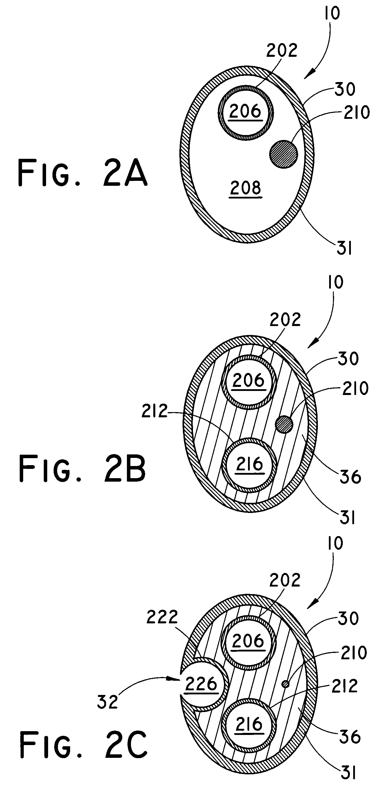
Catheter shaft burst pressure was measured. One end of the shaft to be measured was closed off and the interior of the shaft was pressurized with a measurable source, until a discontinuity or fault (such as a hole) developed in the shaft. The pressure was measured in atmospheres (atm) using a burst tester such as a PT-3070 Burst Tester (Laguna Niguel, Calif.). Each component was pressurized in 1 atm (0.1 MPa) increments using a pressurization rate of 0.40 ml / s starting at 1 atm (0.1 MPa) and held at each pressure for three seconds. A failure was defined as a drop in pressure of 1.50 atm (0.15 MPa) or greater during the three second hold. Four separate burst pressures were measured for each of three component portions of the catheters: a perfluorocarbon liner (202, 212, 222), a thermoformable “figure 8”-shaped tubing having an inner diameter of 0.0215-inches (0.546 mm) with a wall of 0.0025-inches (0.064 mm) (36), and a PEBAX heat-shrink oute...


PUM

PropertyMeasurementUnit
Pressureaaaaaaaaaa
Pressureaaaaaaaaaa
Pressureaaaaaaaaaa

Abstract

Catheter balloon assemblies (10) for delivering a therapeutic agent to a body vessel are provided, as well as related methods of manufacturing and methods of treatment. The catheter balloon assemblies may include a concentrically disposed dual balloon assembly at the distal portion of the catheter having an inner balloon (44), a porous outer balloon (42) concentrically arrayed around the inner balloon and a catheter shaft (30) adapted to deliver a therapeutic agent to the body vessel through the apertures in the outer balloon. Radial outward expansion of the inner balloon may urge the outer balloon into contact with the wall of a body vessel, where the therapeutic agent may be delivered from the catheter shaft through apertures in the outer balloon directly to the wall of the body vessel. Preferably, the catheter balloon assemblies include a stiffening′ member (210) within the proximal portion and/or a plurality of lumens lined with a fluorinated hydrocarbon to independently inflate the inner balloon, deliver the therapeutic agent through the outer balloon and house a wire guide (50). The catheter balloon assemblies may provide improved tractability and/or pushability characteristics.

Description

TECHNICAL FIELDThe present application relates to medical catheters and more specifically to medical catheters useful in delivering a therapeutic agent within a body vessel.BACKGROUNDAlthough many medical conditions are satisfactorily treated by the general systemic administration of a therapeutic agent, the treatment of a many conditions require delivery of the therapeutic agent locally within a body vessel to a selected portion of internal body tissue, without delivery of the therapeutic agent to surrounding tissue or requiring systemic delivery of the therapeutic agent. A systemically administered therapeutic agent may be absorbed not only by the tissues at the target site, but by other areas of the body. As such, one drawback associated with the systemic administration of therapeutic agents is that areas of the body not needing treatment are also affected.Medical delivery catheters provide a minimally invasive means for delivering therapeutic agents to internal body tissue. To p...

Claims


Application Information

Patent Timeline
IPC IPC(8): A61M29/00A61M25/00B29C65/02A61F2/958
CPCY10T29/49865A61M2025/1013A61M25/10A61M2025/1056A61M2025/0004A61M2025/105A61M25/1027
Inventor SCHAEFFER, DARIN G.LENTZ, DAVID CHRISTIAN
Owner COOK MEDICAL TECH LLC
Why Eureka
Try Eureka