
Aqueous curable imprintable medium and patterned layer forming method

a curable imprintable medium and patterned layer technology, applied in the direction of duplicating/marking methods, decorative arts, nanotechnology, etc., can solve the problems of limited shelf life of curable solutions, difficult to achieve the effect of reproducibility, and large time-consuming of curing reactions on substrates, etc., to improve the layer-forming characteristics of medium, improve the miscibility of the components of the medium, and improve the solubility of known photo-acid generators

Active Publication Date: 2011-03-17
ASML NETHERLANDS BV
View PDF13 Cites 10 Cited by
  • Summary
  • Abstract
  • Description
  • Claims
  • Application Information

AI Technical Summary

Benefits of technology

[0012]A photo-acid generator or a photo-base generator is a compound that decomposes upon exposure to light of an appropriate wavelength and thereby releases an acid or a base. The photo-acid generator or photo-base generator is inactive as long as long as it is kept in the dark. The PAG or PBG may also be a compound that releases its acid or base upon exposure to a radical, with the radical being generated from a photo-sensitive compound. It has been found by the inventors of the present invention that the inclusion of a PAG or PBG significantly increases the shelf life of such an aqueous curable imprintable medium. Moreover, it has been found that the reproducibility of relief structures formed using such an aqueous curable imprintable medium has significantly improved by the inclusion of the PAG or PBG. This has the additional advantage that PAG or PBG may be added to the aqueous curable imprintable medium in a concentration that is higher than the acid concentration in the solution disclosed in WO 2008 / 053418, thereby reducing the curing time of the aqueous curable imprintable medium.
[0013]In an embodiment, R1-R3 are individually selected from —OCH3 and —OC2H5 and R4 is selected from —CH3, —C2H5, —OCH3, —OC2H5 and phenyl to reduce the organic content of the patterned layer formed from the aqueous curable imprintable medium. The selection of methoxy or ethoxy groups for R1-R3 allows for a fast hydrolysis of the Si compound as well as for the formation of a network with a high crosslink density.
[0016]An organic solvent may be added to the aqueous curable imprintable medium to improve the layer-forming characteristics of the medium. Typically, the organic solvent has a higher vapor pressure than water at the intended deposition temperature of the aqueous curable imprintable medium to ensure that the solvent evaporates from the medium upon its deposition on a carrier such as a semiconductor substrate. A particularly suitable solvent is propylene glycol monomethyl ether acetate (PGMEA), e.g. because of the good solubility of known photo-acid generators in this solvent. Other suitable solvents for instance include propylene glycol monomethyl ether (PGME) and cyclohexanone. An alcohol may be added to increase the miscibility of the components of the medium. The aqueous curable imprintable medium may further comprise nanoparticles to reduce shrinkage of a patterned layer formed from the medium, and may also comprise a luminescent compound, e.g. a phosphor or luminescent dye, to facilitate functional modification of a semiconductor substrate carrying light-emitting elements such as light-emitting diodes by the formation of patterned layer portions on the light-emitting elements.
[0019]Preferably, the photo acid generator or the photo base generator is present in the medium in a concentration in the range from 0.1 weight % to 1 weight %. In this range, short curing times are obtained without significantly increasing the organic content of the cured patterned layer. For extreme fast curing higher concentrations above 1 wt % may be used.
[0022]The fact that the curing reaction of the curable imprintable medium can be effectively postponed until after the deposition step ensures that a better reproducibility of the formed pattern layer is achieved. Moreover, because no, or at least far less, unwanted curing takes place in the curable imprintable medium, the concentration of the curable compound and / or the catalyst precursor can be increased in said medium, which means that the curing reaction can be completed much more quickly compared to prior art curable imprintable media.

Problems solved by technology

However, it has been found by the inventors of the present invention that curable solutions based on these types of silicon oxide compounds suffer from problems that prevent the wide applicability of these compounds in imprint lithography.
For instance, the curable solution has a limited shelf-life; even at low temperatures, e.g. −20° C., some curing still takes place in the solution, as has been determined by NMR spectroscopy.
Moreover, when applying the solution onto a carrier such as a semiconductor substrate, differences in the reactivity of the solution cause problems in the reproducibility of the patterned layer formations, because the quality, i.e. curing state, of the curable imprintable medium when depositing the medium on the substrate has an impact of the characteristics of the subsequently formed patterned layer.
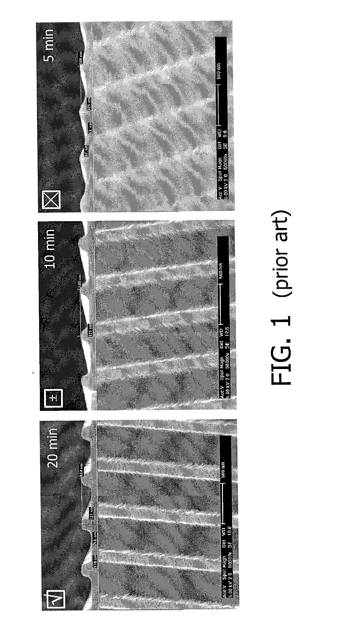
However, this has the drawback that the curing reaction on the substrate can take a considerable time to complete; this is demonstrated in FIG. 1, which shows scanning electron microscope (SEM) images of a grating formed by sol-gel imprint lithography after keeping the layer for 5 minutes in the mould (right pane), 10 minutes in the mould (middle pane) and 20 minutes in the mould (left pane) at room temperature.
The images clearly demonstrate that in order to obtain a good imprint definition, the layer needs to be in the mould in excess of 10 minutes, which can result in excessive total processing times, i.e. a throughput of only a few wafers per hour, or worse in cases where a substrate layer is patterned in a stepwise manner, such as in a step and flash imprint lithography (SFIL) process.

Method used


Image

  • Aqueous curable imprintable medium and patterned layer forming method
  • Aqueous curable imprintable medium and patterned layer forming method
  • Aqueous curable imprintable medium and patterned layer forming method

Examples


example 1

[0046]An aqueous curable medium was formed by mixing the following components:

[0047]40 wt % g TMOS

[0048]50 wt % g MTMS

[0049]9 wt % g water

[0050]<1 wt % PGMEA

[0051]<0.2% PAG121

[0052]The above mixture was deposited by means of spin-coating on a polysilicon wafer, and subsequently imprinted with a PDMS stamp. The mixture and stamp were subsequently exposed to UV light for 6 minutes at 1 mW / cm2, after which the stamp was removed.

example 2

[0053]An aqueous curable medium was formed by mixing the following components:

[0054]45 wt % TEOS

[0055]45 wt % MTES

[0056]9 wt % water

[0057]<1 wt % PGMEA

[0058]<0.2% PAG121

[0059]The above mixture was deposited by means of spin-coating on a polysilicon wafer, and subsequently imprinted with a PDMS stamp. The mixture and stamp were subsequently exposed to UV light for 6 minutes at 1 mW / cm2, after which the stamp was removed.

example 3

[0060]The same mixture as used in example 1 was used. The above mixture was deposited by means of spin-coating on a polysilicon wafer, and subsequently irradiated with UV light for 2.5 minutes at 1 mW / cm2. The irradiated mixture was imprinted with a PDMS stamp for another 2 minutes, after which the stamp was removed.


PUM

PropertyMeasurementUnit
Shrinkageaaaaaaaaaa
Luminescenceaaaaaaaaaa

Abstract

An aqueous curable imprintable medium having at least one curable compound according to Formula 1:wherein R1-R3 are hydrolysable alkoxy groups, and wherein R4 is selected from the group consisting of C1-C6 linear alkyl groups, hydrolysable alkoxy groups and a phenyl group; and a photo-acid generator or a photo-base generator. Such a medium may have an extended shelf-life and may facilitate the formation of highly reproducible patterned layers when used in an imprint lithography process.

Description

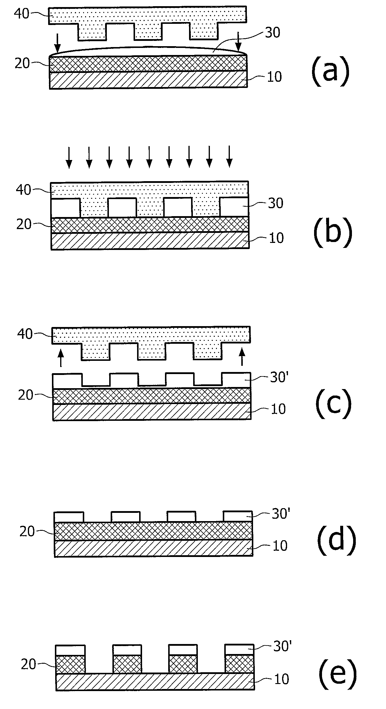
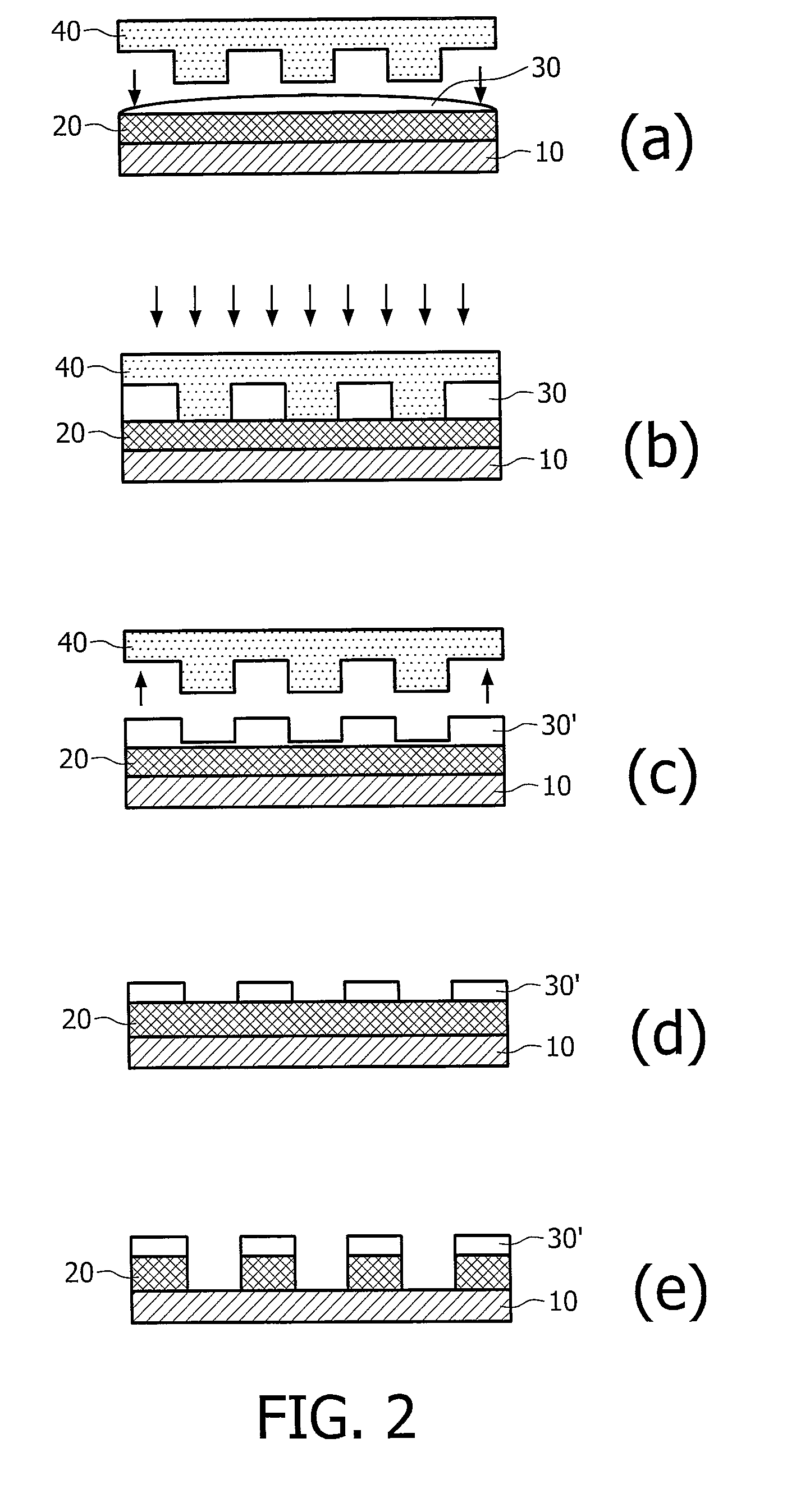
FIELD OF THE INVENTION[0001]The present invention relates to an aqueous curable imprintable medium comprising a curable compound for which the curing is catalyzed by an acid or a base.[0002]The present invention further relates to a method of forming a patterned layer on a substrate from such a medium.BACKGROUND OF THE INVENTION[0003]Imprint lithography is a technique in which a patterned layer such as a masking layer is formed on a semiconductor substrate by the deposition of a curable imprintable medium. The curable imprintable medium is subsequently patterned by imprinting the medium with a patterned stamp, after which the curable imprintable medium is solidified e.g. when exposed to light, e.g. UV-light to initiate the curing reaction in the medium. After the curing reaction is completed, the stamp is removed from the medium to leave a patterned layer on the semiconductor substrate.[0004]This technique has recently drawn considerable attention because it can potentially provide ...

Claims


Application Information

Patent Timeline
IPC IPC(8): B32B3/10C08F2/46B29C35/08
CPCB82Y10/00B82Y40/00Y10T428/24802G03F7/0755G03F7/0002
Inventor VAN BOMMEL, TIESWUISTER, SANDER FREDERIKVERSTEGEN, EMILE JOHANNES KARELHIKMET, RIFAT ATA MUSTAFA
Owner ASML NETHERLANDS BV
Learn More