Thermoplastic Composites and Methods of Making and Using Same

a thermoplastic composite and composite material technology, applied in the field of thermoplastic composite materials, can solve the problems of voids or defects in the matrix coating, the overall production rate of the component is limited, and the difficulty of suppressing, etc., to achieve the effect of reducing the initial capital and facility cost investment, and fast crystallization

Active Publication Date: 2011-04-28
CYTEC TECH CORP
View PDF11 Cites 37 Cited by
  • Summary
  • Abstract
  • Description
  • Claims
  • Application Information

AI Technical Summary

Benefits of technology

[0013]The discovery detailed herein provides lower melting, slower crystallizing semi-crystalline polymer films that are applied to a surface (for example via lamination) of a core containing a tape or tow impregnated with a higher melting, faster crystallizing matrix polymer, and which can be initially processed at a melt process temperature of the surface polymer, but upon cool down crystallizes at rates intermediate to the faster crystallizing matrix polymer. This discovery is useful, for example, in developing an in-situ grade thermoplastic tape and towpreg that can be processed on an Automated Tape Laydown / Automated Fiber Placement (ATL / AFP) machine at comparable speeds as a thermoset based tape, with the exception that no post autoclave or oven step is required after lay down. Cost modeling of the part fabrication has shown that 30% of the fabrication cost (recurring) can be saved by eliminating the post-processing (autoclave / oven) step. Furthermore, this discovery will also reduce the initial capital and facility cost investment to produce large composites.

Problems solved by technology

These low pressures, however, make it difficult to suppress the formation of bubbles within the composite which can result in voids or defects in the matrix coating.
Thus, most processing problems with thermoset composites are concerned with removing entrained air or volatiles so that a void-free matrix is produced.
While current fabrication of large structures utilize robotic placement of the thermoset composite material to increase production rate, its overall production rate for the component is limited by the lengthy cure in the autoclave process step and related operations to prepare the material for that process step.
Although thermoset resins have enjoyed success as in lower volume composites applications, the difficulties in processing these resins has limited their use in larger volume applications.
Thermoplastic compositions, in contrast, are more difficult to impregnate into the reinforcing material because of comparatively higher viscosities.
This method of fabrication is time consuming and cost intensive, and could possibly result in non-uniformity in the lay-up.
Thermoplastic matrix composites have similar key factors as thermoset matrix composites for ATL / AFP machine productivity but since the thermoplastics polymer matrices are generally fully reacted in the tape it lacks “tack” at ambient conditions.
The fully reacted thermoplastics generally have low surface energies making adhesion at room temperature unlikely.
Furthermore, the high performance thermoplastic matrices are in their “glass” state at room temperature making the molecular diffusion mechanism for “tack” virtually impossible.
This process step further reduces the total productivity of the composite part operation.
In general, thermoplastic composites have had limited success to date, due to a variety of factors including high processing temperatures (currently around 400° C.
), high pressures, and prolonged molding times needed to produce good quality laminates.

Method used


Image

  • Thermoplastic Composites and Methods of Making and Using Same
  • Thermoplastic Composites and Methods of Making and Using Same
  • Thermoplastic Composites and Methods of Making and Using Same

Examples


embodiment 1

2. A thermoplastic composition , wherein the fibrous substrate is chosen from carbon fibers, glass fibers, aramid fibers, and mixtures thereof and comprises from 50 to 80 weight percent of the total composite weight.

3. A thermoplastic composition according to embodiments 1 or 2, wherein the fibrous substrate is polyacrylonitrile (PAN) based carbon fiber.

4. A thermoplastic composition according to any of the preceding embodiments, wherein the fibrous substrate is in the form of a uni-tape web, non-woven mat or veil, fiber tow, or fabric material.

5. A thermoplastic composition according to any of the preceding embodiments, wherein the high performance polymer is chosen from polyaryletherketones (PAEK); PAEK blends; polyimides; and polyphenylenesulfides (PPS).

embodiment 5

6. A thermoplastic composition , wherein the polyaryletherketone is chosen from: polyetheretherketone (PEEK), polyetheretherketoneketone (PEEKK), polyetherketoneketone (PEKK) having a terephthaloyl to isophthaloyl ratio of 70:30 to 100:0, polyetherketone (PEK), and polyetherketoneketoneetherketone (PEKKEK).

7. A composition according to embodiment 5, wherein the polyaryletherketone is chosen from APC-2® PEEK, Cypek®FC, and Cypek®HT.

8. A thermoplastic composition according to embodiment 5, wherein the polyaryletherketone blend comprises PEI, PES, PPS and mixtures thereof.

9. A thermoplastic composition according to embodiment 5, wherein the polyimide is Aurum® TPI.

10. A thermoplastic composition according to any of the preceding embodiments, wherein the surface layer polymer is chosen from: polyetherimide (PEI); polyaryletherketone polymer blended with PEI, PES, PPS, polyimide, and mixtures thereof; polyaryletherketones; polyimides; and mixtures thereof.

embodiment 10

11. A thermoplastic composition , wherein the PAEK polymer blend comprises PEEK or PEKK and diphenylsulfone.

12. A thermoplastic composition according to embodiment 10 or 11, wherein the PAEK is PEKK having a terephthaloyl to isophthaloyl ratio of 0:100 to 70:30.

13. A thermoplastic composition according to any of embodiments 10 to 12, wherein the surface layer polymer comprises Cypek®DS-E or Cypek®DS-M.

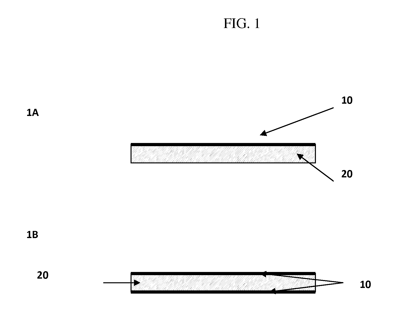
14. A thermoplastic composition according to any of the preceding embodiments, wherein the surface layer polymer layer is from 1 to 20 microns thick.


PUM

PropertyMeasurementUnit
Tmaaaaaaaaaa
thickaaaaaaaaaa
melt viscositiesaaaaaaaaaa

Abstract

Thermoplastic composites having a core composite layer including a fibrous substrate and one or more high performance polymer, and a surface layer polymer applied to at least one surface of the core composite layer, which forms a polymer blend with the high performance polymer thereby imparting improved toughness and processing times, and methods for making and using same, are provided herein.

Description

CROSS-REFERENCE TO RELATED APPLICATIONS[0001]This application claims benefit of priority from U.S. Provisional Application No. 61 / 245,399, filed Sep. 24, 2009, which is incorporated by referenced herein in its entirety.BACKGROUND OF THE INVENTION[0002]1. Field of the Invention[0003]The subject matter of the present invention relates to thermoplastic composite materials and prepregs used for creating structures that have a high strength-to-weight ratio. More particularly, in certain embodiments the present invention relates to layered thermoplastic composites for use in rapid lamination and forming processes, which composites possess an interlayer region containing at least one polymer that is high in crystallinity and either partially or fully crystallizes during the process window of the rapid lamination or forming process, and an outerlayer region containing a polymer that has low or no crystallization and is miscible and / or compatible with the polymer of the interlayer region, an...

Claims


Application Information

Patent Timeline
Patent Type & Authority Applications(United States)
IPC IPC(8): B32B27/06B32B27/04B32B27/12B05D1/36B05D1/08B32B38/08
CPCB29C70/086B29C70/88B29K2071/00Y10T428/265B29K2081/04B29K2081/06B29K2101/12B29K2079/085Y10T428/249921Y10T428/249945Y10T428/249946Y10T428/249947Y10T428/24995
Inventor PRATTE, JAMES F.ROGERS, SCOTT A.PONSOLLE, DOMINIQUE
Owner CYTEC TECH CORP
Why Eureka
Try Eureka