

Carbon fiber and catalyst for production of carbon fiber
a carbon fiber and catalyst technology, applied in the direction of physical/chemical process catalysts, cell components, metal/metal-oxide/metal-hydroxide catalysts, etc., can solve the problems of low device efficiency, difficult to inexpensively produce carbon fiber with desired properties, and lack of electric conductivity, so as to achieve low cost, increase the generation efficiency of carbon fiber per catalyst mass, and reduce the effect of conten
- Summary
- Abstract
- Description
- Claims
- Application Information
AI Technical Summary
Benefits of technology
Problems solved by technology
Method used
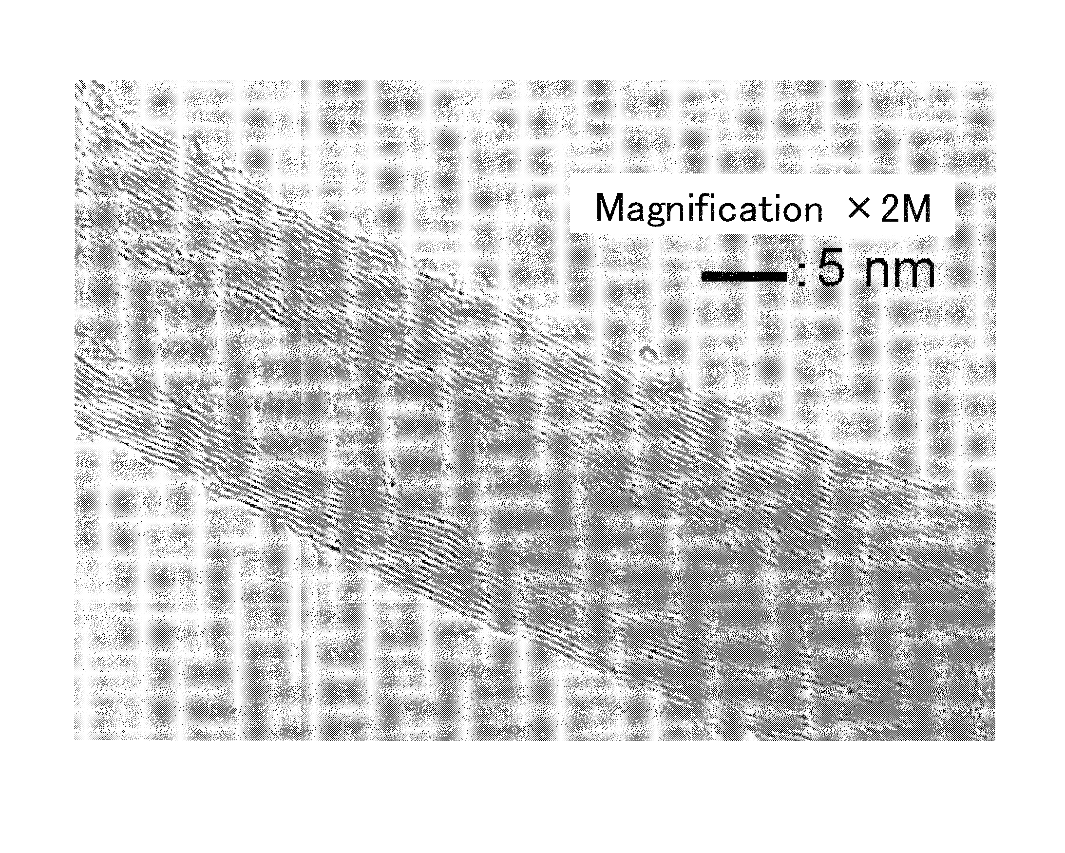
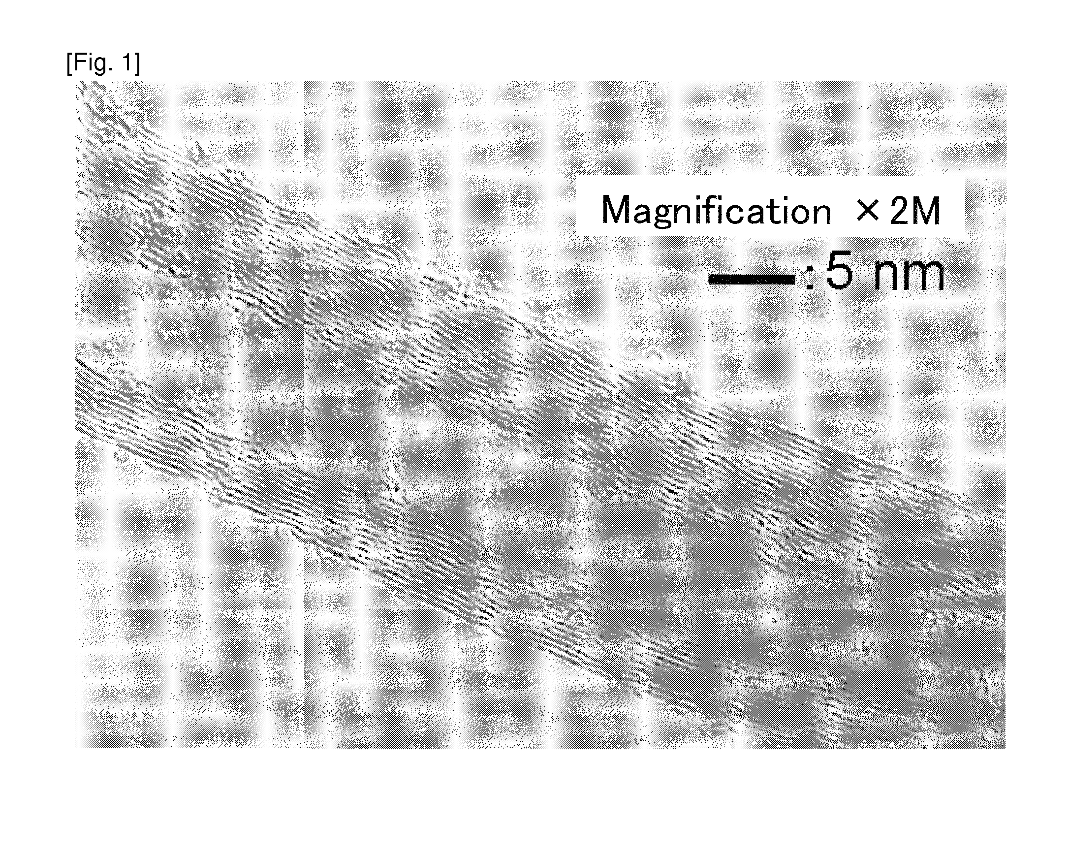
Image

Examples
example 1
Fe (70)-Co (30)-Ti (10)-Mo (10) / Alumina
[0122]In 0.95 part by mass of methanol, 1.25 parts by mass of iron (III) nitrate nonahydrate and 0.38 part by mass of cobalt (II) nitrate hexahydrate were added and dissolved, and then 0.11 part by mass of titanium (IV) tetra-n-butoxide tetramer and 0.08 part by mass of hexaammonium heptamolybdate tetrahydrate were added and dissolved so as to obtain a solution A.
[0123]The solution A was dripped and mixed with 1 part by mass of intermediate alumina (made by Sumitomo Chemical Co., Ltd.; AKP-G015). After the mixing, it was vacuum-dried at 100 degrees cent. for 4 hours. After the drying, it was crushed in a mortar and pestle so as to obtain a catalyst. In the catalyst, the molar ratio of Co / Fe was 0.3 / 0.7, the content of Mo was 10% by mol and the content of Ti was 10% by mol with respect to the total amount of Fe and Co, and the total supported amount of Fe and Co with respect to the intermediate alumina was 25% by mass.
[0124]The weighed catalyst ...
example 2
Fe (90)-Co (10)-V (10)-Mo (10) / Alumina
[0126]In 0.95 part by mass of methanol, 1.62 parts by mass of iron (III) nitrate nonahydrate and 0.13 part by mass of cobalt (II) nitrate hexahydrate were added and dissolved, and then 0.05 part by mass of ammonium metavanadate and 0.08 part by mass of hexaammonium heptamolybdate tetrahydrate were added and dissolved so as to obtain a solution B.
[0127]The solution B was dripped and mixed with 1 part by mass of intermediate alumina (Sumitomo Chemical Co., Ltd.; AKP-G015). After the mixing, it was vacuum-dried at 100 degrees cent. for 4 hours. After the drying, it was crushed in a mortar and pestle so as to obtain a catalyst. In the catalyst, the molar ratio of Co / Fe was 0.1 / 0.9, the content of Mo was 10% by mol and the content of V was 10% by mol with respect to the total amount of Fe and Co, and the total supported amount of Fe and Co with respect to the intermediate alumina was 25% by mass.
[0128]Using the catalyst, a carbon fiber was obtained b...
example 3
Fe (70)-Co (30)-V (10)-Mo (10) / Alumina
[0129]In 0.95 part by mass of methanol, 1.25 parts by mass of iron (III) nitrate nonahydrate and 0.38 part by mass of cobalt (II) nitrate hexahydrate were added and dissolved, and then 0.05 part by mass of ammonium metavanadate and 0.08 part by mass of hexaammonium heptamolybdate tetrahydrate were added and dissolved so as to obtain a solution C.
[0130]The solution C was dripped and mixed with 1 part by mass of intermediate alumina (Sumitomo Chemical Co., Ltd.; AKP-G015). After the mixing, it was vacuum-dried at 100 degrees cent. for 4 hours. After the drying, it was crushed in a mortar and pestle so as to obtain a catalyst. In the catalyst, the molar ratio of Co / Fe was 0.3 / 0.7, the content of Mo was 10% by mol and the content of V was 10% by mol with respect to the total amount of Fe and Co, and the total supported amount of Fe and Co with respect to the intermediate alumina was 25% by mass.
[0131]Using the catalyst, a carbon fiber was obtained b...
PUM
| Property | Measurement | Unit |
|---|---|---|
| diameter | aaaaa | aaaaa |
| diameter | aaaaa | aaaaa |
| diameter | aaaaa | aaaaa |
Abstract
Description
Claims
Application Information