Methods and systems for making battery electrodes and devices arising therefrom

a battery electrode and manufacturing method technology, applied in the direction of electrode manufacturing process, mechanical vibration separation, nuclear engineering, etc., can solve the problems of reducing the performance and reducing the efficiency of the battery electrod

Inactive Publication Date: 2011-06-16
MOLECULAR NANOSYST
View PDF7 Cites 45 Cited by
  • Summary
  • Abstract
  • Description
  • Claims
  • Application Information

AI Technical Summary

Problems solved by technology

Problems exist with the slurry coating method, whether by doctor blade or by slot die process, in that generally only one layer can be deposited upon the surface of the substrate.
Depositing additional layers using doctor blade and slot die methods runs the risk of delaminating the earlier deposited layers due to the forces applied against the substrate as it is pulled across the doctor blade or slot die head.
Another problem with traditional battery making methods is that because thick layers are deposited to achieve the desired energy density for the electrode, the period of time it takes for the solvent to evaporate from the deposited slurry is considerable.
Stratification leads to less than optimal performance because the different particles within the electrode matrix are not spatially distributed evenly.
Not wishing to be bound by theory, it is believed that nano-scale particles present a problem, however, because they have a greater number of particles per unit mass than micrometer scale particles typically used in commercially available cells.
Internal resistance causes power loss through heating and can contribute to thermal runaway and flame.
The inside diameter of carbon nanotubes, compared to their outside dimension, greatly reduces the number of effective interfaces in the electrical conductive path.
A problem exists, however, in using carbon nanotubes in that they tend to aggregate.
Aggregation can pose a problem with coating surfaces to form electrodes using a slurry based process.

Method used


Image

  • Methods and systems for making battery electrodes and devices arising therefrom
  • Methods and systems for making battery electrodes and devices arising therefrom
  • Methods and systems for making battery electrodes and devices arising therefrom

Examples


example 1

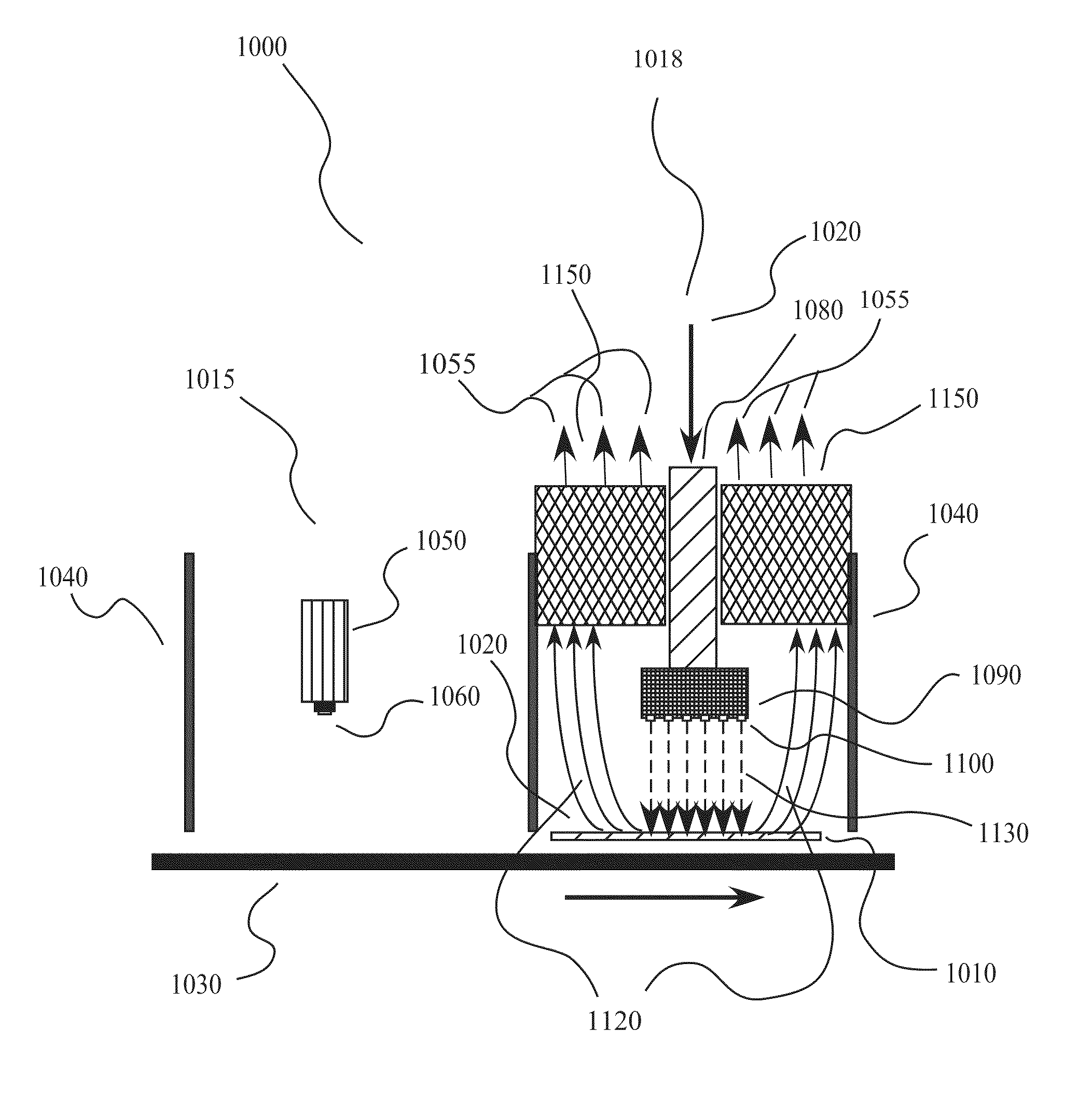
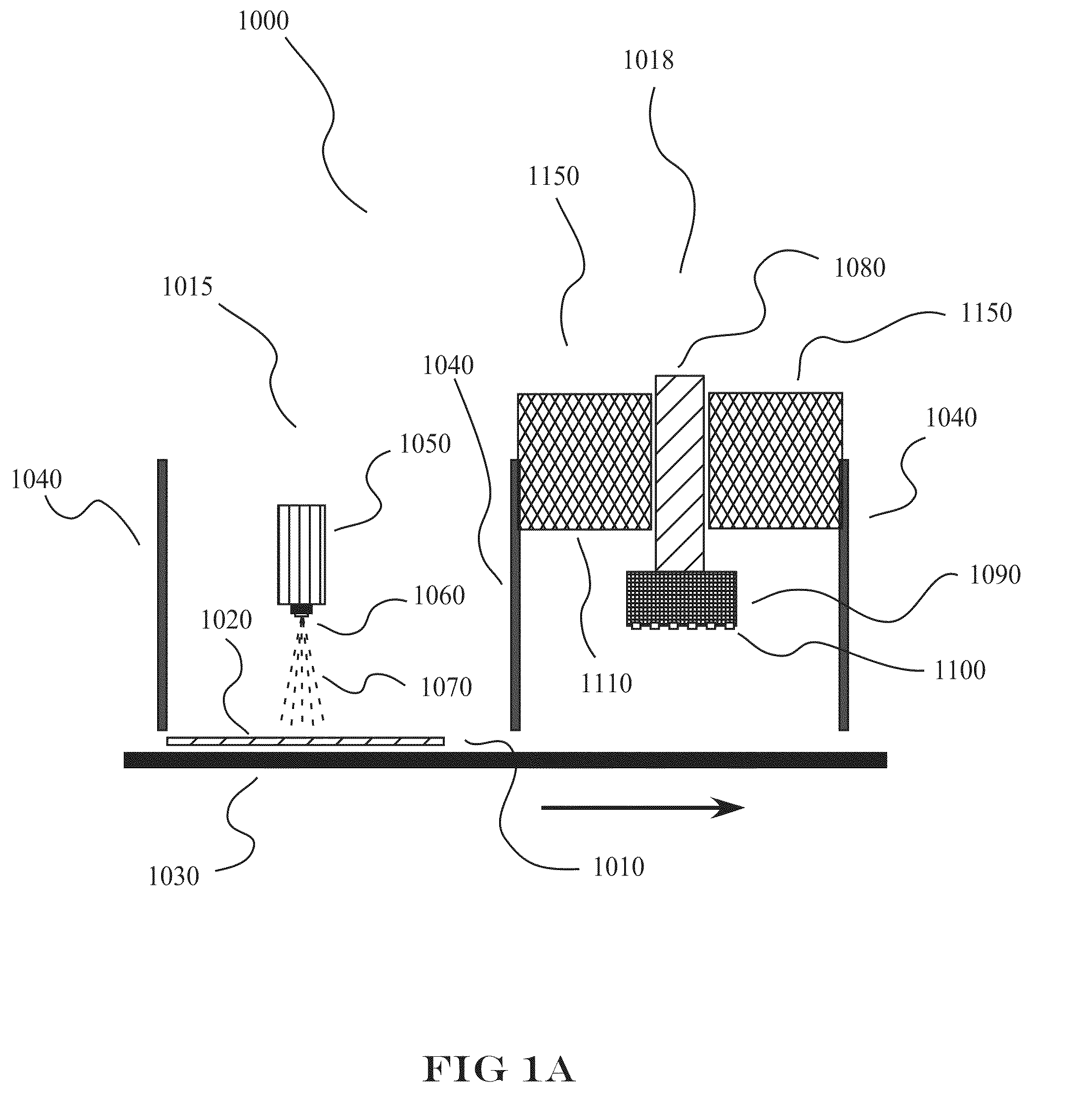
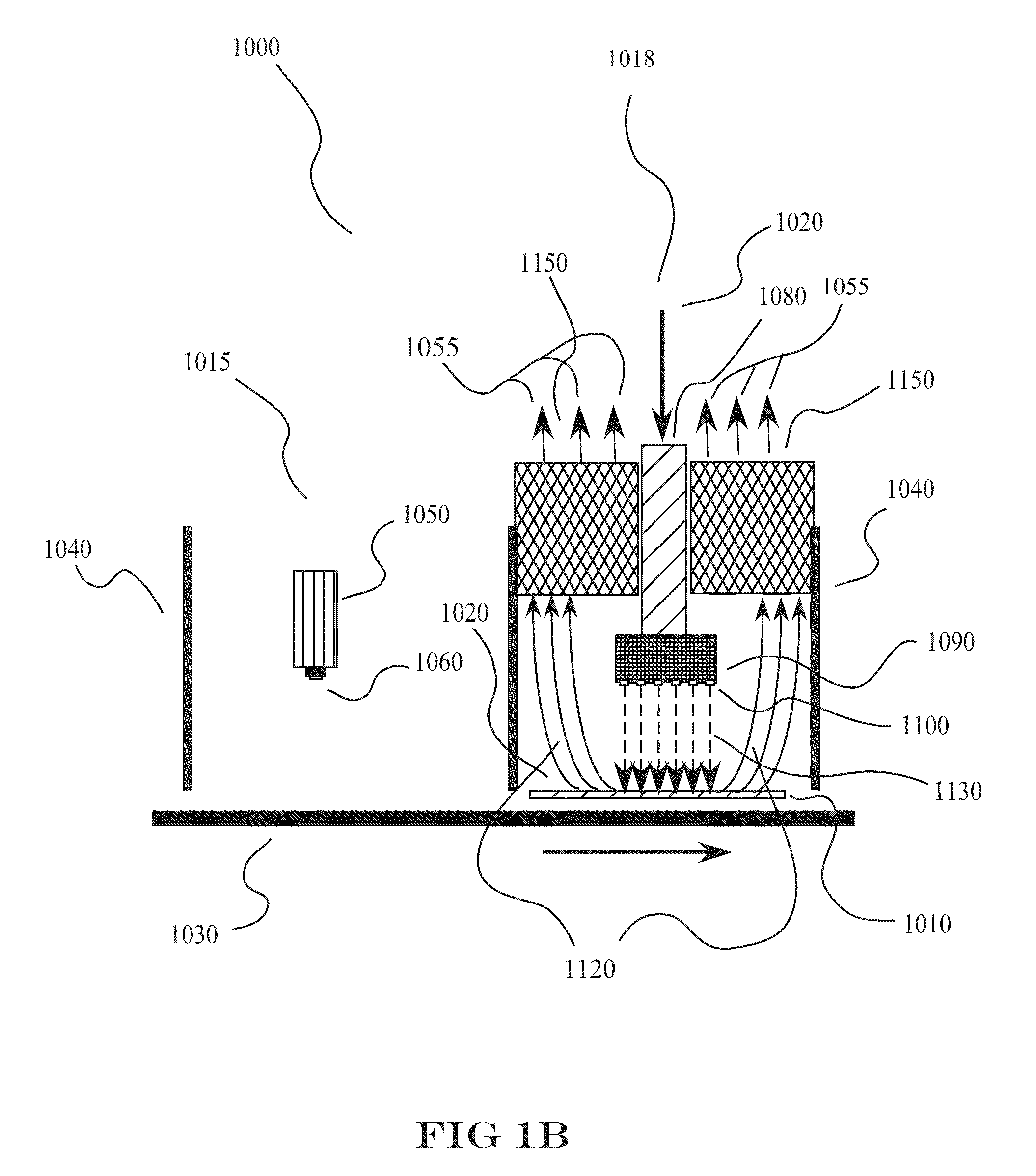
Basic Spray / Dry Process

[0083]Basic spray / dry method was tested using an airbrush filled with a suspension containing:

[0084]Spraying was performed manually with a back and forth motion of the spray head parallel to the surface of the substrate. Approximately 40 passes were made to load the surface to a desired amount.

example 2

Multi-step Spray / Dry Process

Example 3

Fabrication of Electrodes into a Cell

[0085]Circles were cut from each type of electrode (cathode / anode) in a size to fit into a pouch. A porous polymer sheet was placed between the electrodes as they were layered into the pouch. Electrolyte (LiPF6) was added prior to vacuum sealing the pouch to form a pouch cell.

example 4

Testing of Cell

[0086]The following protocol was followed to test cells made with the electrodes of the invention:[0087]a) Measure open circuit voltage (OCV) (10 sec)[0088]b) Apply 1 sec current pulse (0.5 mA for coin cells, 5-10 mA for pouch cells)[0089]c) Measure voltage drop between OCV and the first 10 msec of applied pulse[0090]d) Impedance testing: A few special cells, especially large pouch cells:[0091]e) Measure impedance from 1000 kHz to 0.01 Hz

[0092]Anode Half-cells[0093]a) Resistance test[0094]b) Initial capacity test in constant current mode (3 cycles, starting with discharge cycle, each cycle running at 25 mA / g and then lowering to 12.5 mA / g until voltage limit is reached—designated “25+12.5 mA / g”)[0095](a) For graphite ½-cells, voltage limits are 0.01V and 1.5V[0096](b) For silicon ½-cells, voltage limits 0.07V to 1.0V[0097]c) Resistance test[0098]i) Power test* up to 10 mA total current[0099]ii) followed by power test up to 20 mA, if charge withdrawn at 10 mA step is ≧...


PUM

PropertyMeasurementUnit
frequenciesaaaaaaaaaa
diameteraaaaaaaaaa

Abstract

The invention provides, in preferred embodiments, methods, systems, and devices arising therefrom for making battery electrodes, in particular, for lithium-ion batteries. Unlike conventional slurry coating methods that use mechanical means to coat thick pastes of active material, other materials, and solvent(s) onto a substrate, the invention provides for a method to produce electrode coatings onto support in a multi-layer approach to provide highly uniform distribution of materials within the electrode. Problems of differential sedimentation of particles in slurries found in conventional methods are minimized with the methods of the present invention. Also included are systems for producing in large-scale the battery electrodes of the invention. Further included are electrodes produced by the methods and systems described herein.

Description

FIELD OF THE INVENTION[0001]The invention generally relates to the field of battery electrode manufacturing, preferably lithium-ion battery electrode manufacturing. The invention generally pertains to the field of energy storage, batteries, lithium-ion (Li-ion) batteries, advanced vehicles technology, and reduction of national reliance upon foreign petroleum products. The invention also relates to manufacturing systems for applying a coating or coatings to surfaces of substrates. The invention further relates to the field of energy efficiency, and environmental protection.BACKGROUND[0002]Lithium ion batteries play an important part in today's high-technology world. Reaching new markets, lithium ion batteries offer the promise of high energy capacity / high power output in relatively lightweight and compact formats when compared to traditional lead acid, nickel metal anhydride, or nickel cadmium batteries.[0003]Traditional methods for making lithium ion batteries generally include the ...

Claims


Application Information

Patent Timeline
Patent Type & Authority Applications(United States)
IPC IPC(8): B05D5/12C23C14/54B82Y30/00B82Y40/00
CPCH01M4/0419Y02E60/122H01M10/052Y02E60/10B05D5/12H01M4/04H01M4/139H01M10/0525
Inventor PENG, SHUFUPAN, LAWRENCE S.
Owner MOLECULAR NANOSYST
Why Eureka
Try Eureka