

Photocatalyst and reducing catalyst using the same
a photocatalyst and catalyst technology, applied in the direction of organic compound/hydride/coordination complex catalyst, physical/chemical process catalyst, metal/metal-oxide/metal-hydroxide catalyst, etc., can solve the problem that the photocatalytic reaction cannot be obtained with such a structur
- Summary
- Abstract
- Description
- Claims
- Application Information
AI Technical Summary
Problems solved by technology
Method used
Image

Examples
example 1
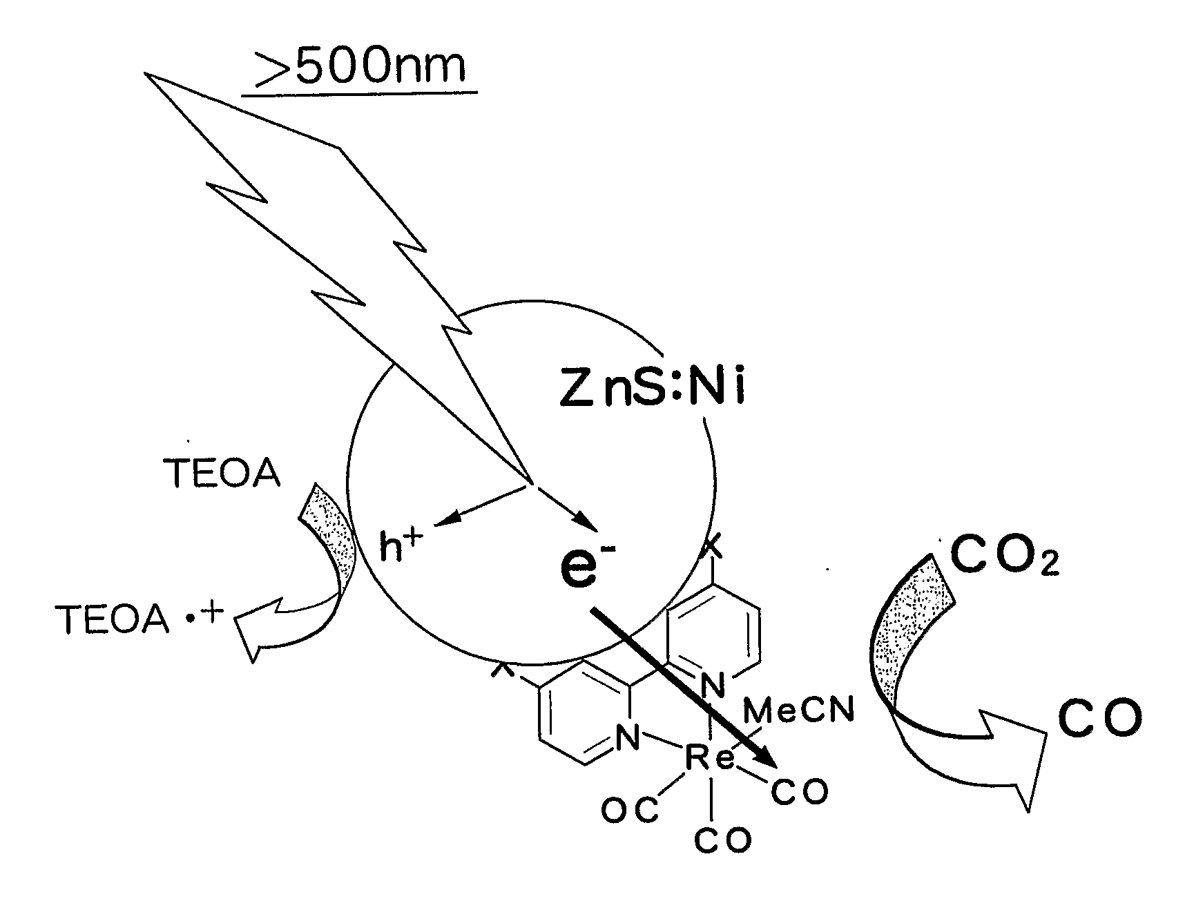
[0023]Zinc (II) nitrate 6 hydrate and nickel (II) nitrate 6 hydrate were dissolved in distilled water. Thereafter, an aqueous solution dissolving sodium sulfide 9 hydrate was added, followed by stirring for 2 hours. At this time, the total metal ion concentration in the solution was set to be constant at 0.1 mol / L and the ratio of nickel was set at 0.1 wt % relative to the total metal concentration. The stirred suspension solution was centrifuged and redispersed. This operation was repeated three times. After the supernatant was removed, the resultant substance was dried under vacuum. The solid matter obtained was pulverized in a mortar to obtain a nickel-containing zinc sulfide semiconductor powder. X-ray diffraction analysis performed by a diffractometer (RINT-TTR, Rigaku) confirmed that only a crystalline phase of ZnS is present in the powder. Furthermore, measurement of diffuse reflection by a spectrophotometer (UV-3600•ISR-3100, Shimadzu Corporation) confirmed that the powder a...
example 2
[0025]Zinc (II) nitrate 6 hydrate and copper (II) nitrate 3 hydrate were dissolved in distilled water. Thereafter, sodium sulfide 9 hydrate was added, followed by stirring for 2 hours. At this time, the total metal ion concentration of the solution was set to be constant at 0.1 mol / L and the ratio of copper was set at 4.5 wt % relative to the total metal concentration. The suspension solution stirred was centrifuged and redispersed. This operation was repeated three times. After the supernatant was removed, the resultant substance was dried under vacuum. The solid matter obtained was pulverized in a mortar to obtain a copper-containing zinc sulfide semiconductor powder.
[0026]Thereafter, the powder (500 mg) and 4 mg of a rhenium complex ((Re(dcbpy)(CO)3MeCN)) were stirred in methanol for 12 hours and dried under vacuum to synthesize a catalyst having the semiconductor and the metal complex joined therein.
example 3
[0027]Tantalum (V) oxide (manufactured by Wako Pure Chemical Industries Ltd.) was treated in gas flow prepared by mixing ammonia and argon each at a flow rate of 250 sccm, at 750° C. for 12 hours to obtain an orange powder. X-ray diffraction analysis confirmed that crystalline phases of Ta3N5, TaON, and Ta2O5 are present as a mixture in the powder. Spectrophotometry confirmed that the powder absorbs light having a wavelength of 620 nm or less. The powder (500 mg) and 2 mg of a rhenium complex ((Re(dcbpy)(CO)3MeCN)) having a carboxybipyridine ligand were stirred in methanol for 12 hours and dried under vacuum to synthesize a catalyst having the semiconductor and the metal complex joined therein.
PUM
| Property | Measurement | Unit |
|---|---|---|
| Energy | aaaaa | aaaaa |
| Molar density | aaaaa | aaaaa |
| Molar density | aaaaa | aaaaa |
Abstract
Description
Claims
Application Information