Radiant heating using heater coatings

a technology of heating and heating coils, applied in the field of radiant heating using heater coatings, can solve the problems of heat transfer, inefficient and complicated hydronic systems, complex installation of hydronic systems, etc., and achieve the effects of low manufacturing cost, convenient installation, and efficient energy utilization

Inactive Publication Date: 2011-08-04
THERMOCERAMIX
View PDF52 Cites 26 Cited by
  • Summary
  • Abstract
  • Description
  • Claims
  • Application Information

AI Technical Summary

Benefits of technology

[0020]Thermally sprayed heating layers offer very efficient energy utilization for radiant heating systems because they are distributed over a large area. In addition, manufacturing costs are low because the heaters can be deposited directly on a structural material, such as a sub-floor or a flooring overlay material, at the factory where the materials are made. The heating system is consequently simpler, cheaper and generally easier to install as compared to conventional radiant heating systems.

Problems solved by technology

Hydronic systems are inefficient and complicated because frequently multiple fluid circuits are necessary for one floor since the water becomes too cold to uniformly heat a given floor in a single pass.
Hydronic systems often are complex to install because they consist of many valves, manifolds, pumps and fluid controls.
Heat transfer is a problem with electric wire systems because all the heat energy that is ultimately absorbed by humans in the room must be generated along a thin wire.
These systems exhibits improved efficiency over wire-based heaters, but they have not been widely used due to the high cost of the materials and the difficulties in installing and using these systems for certain applications, such as in non-rectangular and / or irregularly-shaped floors.

Method used


Image

  • Radiant heating using heater coatings
  • Radiant heating using heater coatings
  • Radiant heating using heater coatings

Examples


Embodiment Construction

[0039]This is a continuation-in-part application of U.S. application Ser. No. 12 / 156,438, filed on May 30, 2008, the entire contents of which is incorporated herein by reference.

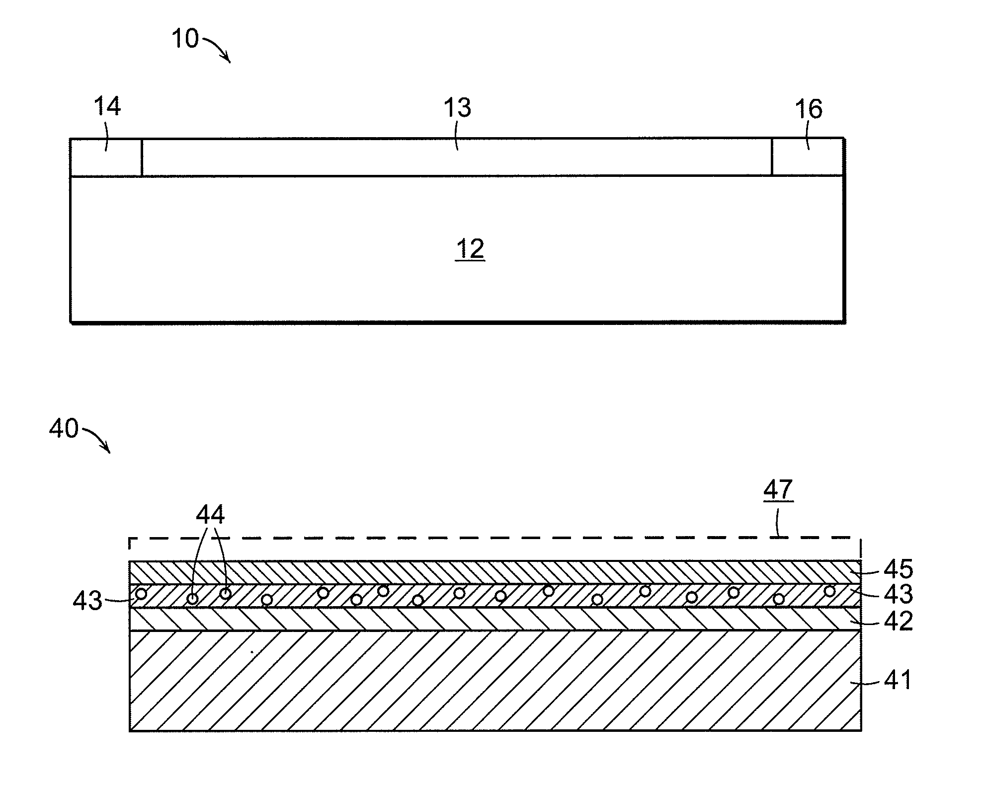
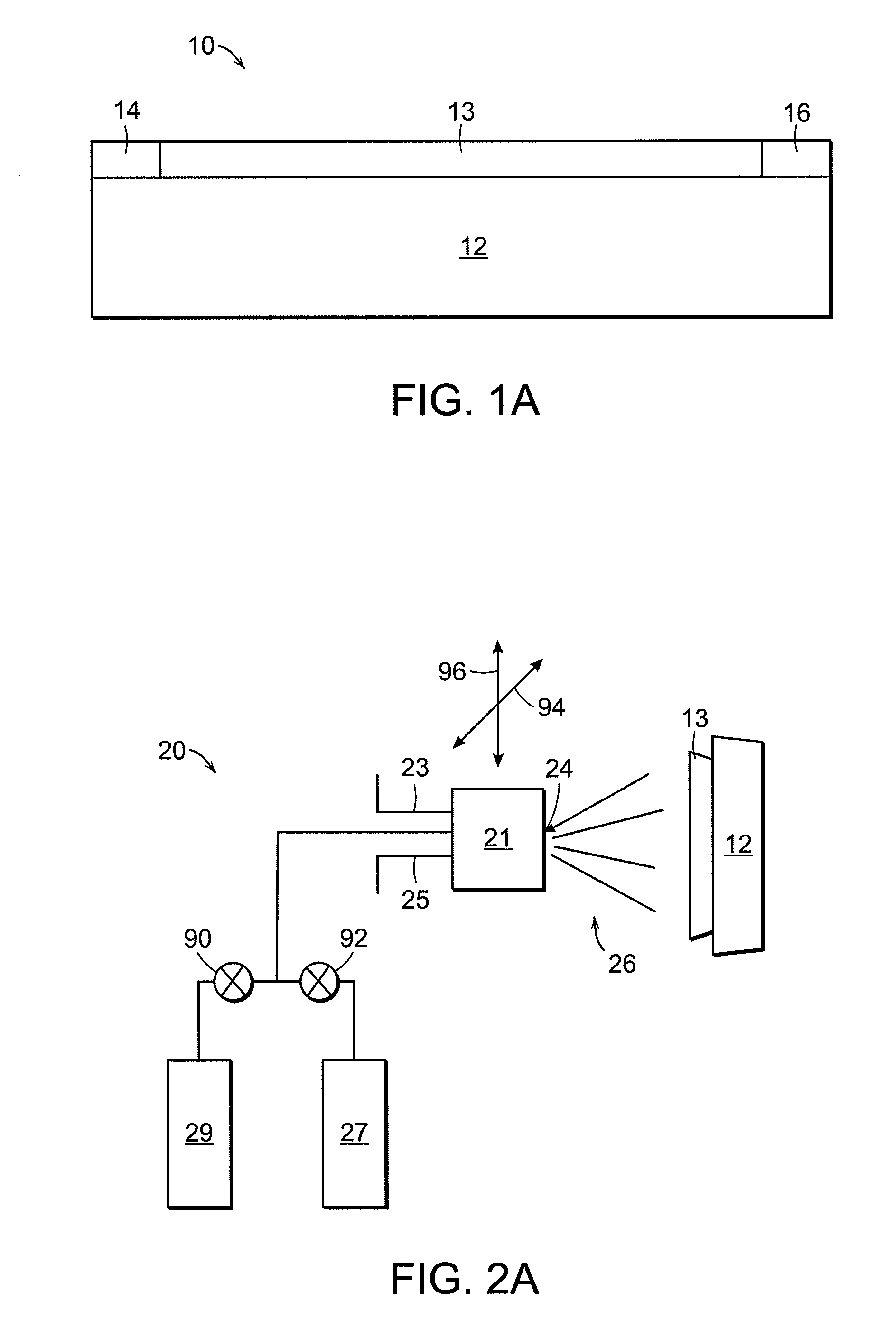
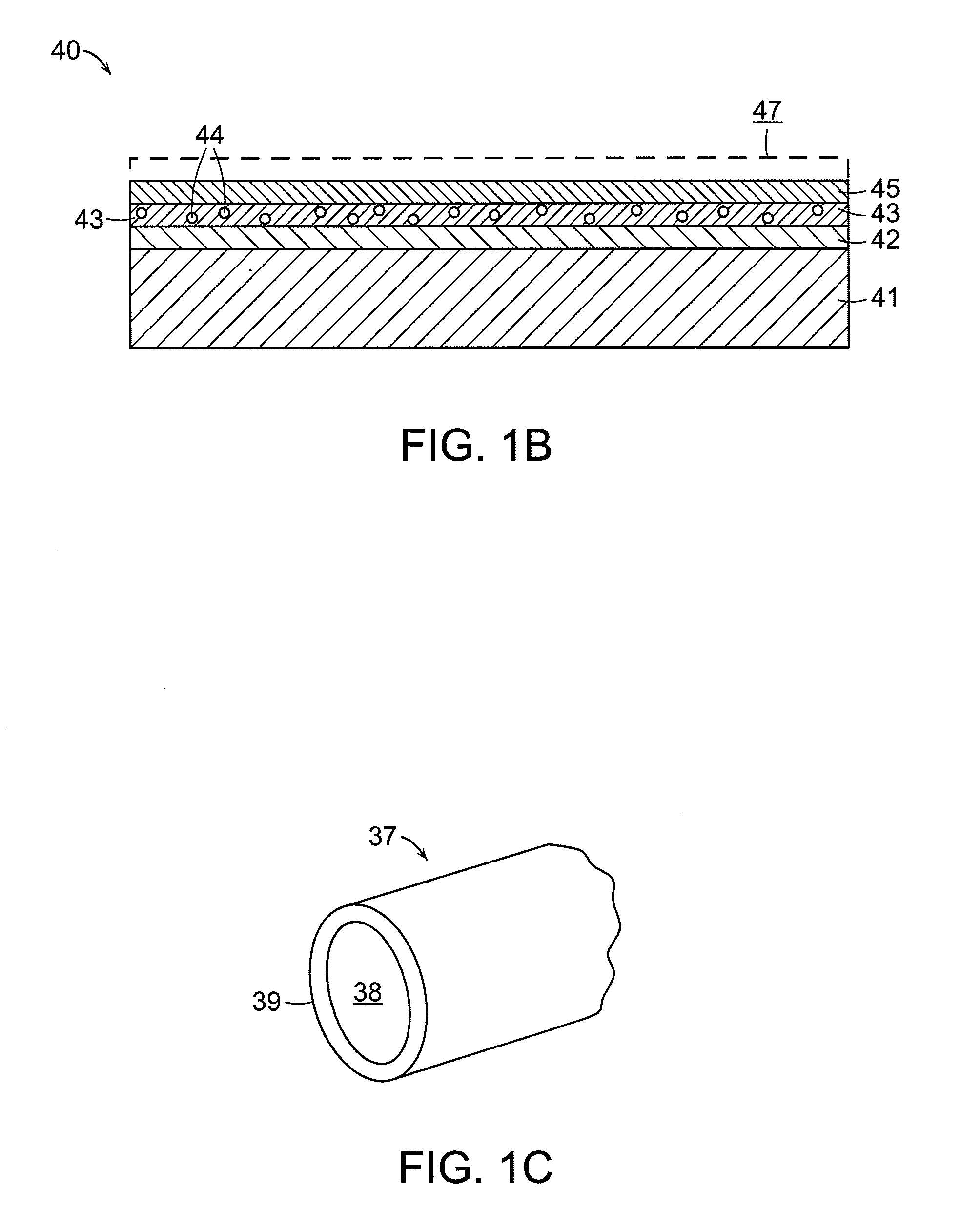
[0040]Referring now to FIG. 1A, a preferred embodiment of a radiant heating system is shown generally at 10, and includes a backer board substrate 12, a patterned resistive material 13 disposed on the substrate 12, and interconnects 14 and 16. Backer board substrate 12 may be any of a number of materials, but in a preferred embodiment it is formed of a cementous material that is designed to underlay tile or other floor finish materials.

[0041]The resistive heating material 13 is preferably formed by a thermal spray process. Thermal spray is a versatile technology for depositing coatings of various materials, including metals and ceramics. It includes systems that use powder as feedstock (e.g., arc plasma, flame spray, and high velocity oxy-fuel (HVOF) systems), systems that use wire as feedstock (e.g., arc wi...


PUM

PropertyMeasurementUnit
heightaaaaaaaaaa
heightaaaaaaaaaa
heightaaaaaaaaaa

Abstract

A radiant heating system comprises a thermally sprayed resistive heating layer bonded to an underlayment building material substrate. The substrate can comprise a sub-flooring material and the heating system can comprise a radiant floor heating system. The resistive heating layer can be thermally sprayed directly onto a sub-floor or similar underlayment material, including cementitious backing material or a sound reduction board. A finished floor surface, such as a tile, wood or laminate surface, can be provided over the substrate and thermally sprayed heater to provide a radiant floor heater. In other embodiments, a radiant heating system includes a thermally sprayed heater bonded to a flooring overlay, such as a laminate board, to a heater insert, such as a flexible polymer film or a mica-based material, or to a concrete substrate. Methods of fabricating radiant heating systems include thermally-spraying a resistive material on a sub-floor or flooring overlay.

Description

BACKGROUND OF THE INVENTION[0001]Radiant heat derives from electromagnetic radiation that emanates from matter, or more specifically from the atoms that make up the matter. The atoms are electrically charged with the charge distributed over its volume such that on average an associated tiny electrical field called a dipole exists. Since all atoms in matter vibrate, the dipoles associated with the atoms also vibrate, and thus emanate an electromagnetic field. The frequency of the emanated field is equal to the atom's frequency of vibration, which we characterize as its temperature. Thus, radiant energy from all matter is proportional to its temperature, and all matter with a temperature above absolute zero radiates.[0002]Atoms not only radiate electromagnetic radiation, they also absorb it. This is because atomic charge responds to a superimposed electric field. Therefore, atoms that experience an electromagnetic field with a higher frequency will begin to vibrate at that frequency a...

Claims


Application Information

Patent Timeline
Patent Type & Authority Applications(United States)
IPC IPC(8): F27D11/12H01C17/02
CPCF27D11/12Y10T29/49083H01C17/02F24D13/024H05B2203/032H05B2203/013H05B3/267H05B2203/026E04F15/182H05B3/26H05B3/283F24D13/02H05B3/34
Inventor ABBOTT, RICHARD C.
Owner THERMOCERAMIX
Why Eureka
Try Eureka