U-Shape And/or Nozzle U-Loop Fermenter And Method Of Fermentation

a technology of u-loop fermenter and nozzle, which is applied in the direction of specific use bioreactor/fermenter, chemical/physical/physicochemical process, biomass after-treatment, etc., can solve the problems of gaseous substrate solubility, fermentation broth, oxygen or methane addition to fermentation liquid, etc., to achieve the effect of increasing the mass transfer and solubility of substrate gases, increasing the pressure, and further optimising the fermentation process

Inactive Publication Date: 2011-10-06
UNIBIO AS
View PDF2 Cites 25 Cited by
  • Summary
  • Abstract
  • Description
  • Claims
  • Application Information

AI Technical Summary

Benefits of technology

[0036]The object of the invention is to improve the mass transfer of the gaseous substrates into the liquid phase where they are available to the biocatalysts (e.g. the microorganisms) in an energy efficient manner.
[0037]It is also an object of the invention to improve the efficiency of the waste gas removal by improving waste gas transfer from the liquid phase into the gas phase for removal from the fermenter, even when the fermenter is operated under increased pressure.

Problems solved by technology

The addition of gaseous substrates such as oxygen or methane to fermentation liquid is problematic, since the microorganisms cannot use the gases directly.
A generic problem in fermentation processes is therefore to solubilise enough of the gaseous nutrients in the broth to satisfy the demands of the microorganisms, particularly if the population or concentration of microorganisms is large (and the demand for gaseous substrates is high), or if the fermentation temperature is high, which tends to lower the solubility of the gaseous substrates in the fermentation broth.
Since microorganisms are sensitive living cells, significant reduction of the temperature is not possible without affecting the growth rate of the microorganisms.
Even so, many fermentation processes are limited by insufficient transfer of gases into the liquid phase.
This compression of gases requires significant amounts of energy.
But the vigorous mixing in order to create small gas bubbles and ensure optimal mixing in the tank also requires the use of excessive energy and further implies a significant heating of the fermentation liquid.
The excessive use of energy renders this type of reactor uneconomical, especially for cheap products such as microbial cells, which are currently sold as animal food or fish food.
Compression of air usually requires significant amounts of energy.
Airlift reactors have a relatively poor exploitation of the injected gas.
It is often difficult to obtain a good and quick release of the gas bubbles from the fermentation liquid at the top of the reactor and separation of the gas phase thus produced (which may be rather foaming) from the liquid phase before the liquid flows into the down-flow part of the reactor.
However, contrary to conventional loop reactors, the liquid circulation is effected by means of an in-line pump.
Furthermore, the U-shape reactor provides for a long contact time between the gas and liquid phases, as the injected gas is present both in the down-flow part and in the up-flow part of the loop.
This tendency contributes to making conventional airlift reactors ineffective inasmuch as the bubbles become larger and larger upward through the up-flow part, partly due to coalescence and partly due to a reduced hydrostatic pressure.
This construction of the fermenter may result in gas pockets building up in the top of the horizontal part of the U-loop, and thus, reducing the liquid volume in the fermenter and reducing the overall productivity of the fermenter.
Nevertheless, the transfer of gases between the gas phase and the liquid phase in such fermenters is still too poor for producing inexpensive products in a fermentation process.
One problem with increasing the pressure in the fermenter is that the release of waste gases from the fermentation liquid is reduced when increasing the pressure.
The energy employed for pressurising the headspace cannot be recovered.
A high concentration of carbon dioxide in the fermentation liquid causes a reduced productivity of the cells in the fermenter and thereby a reduced overall productivity in the fermentation process.

Method used


Image

  • U-Shape And/or Nozzle U-Loop Fermenter And Method Of Fermentation
  • U-Shape And/or Nozzle U-Loop Fermenter And Method Of Fermentation
  • U-Shape And/or Nozzle U-Loop Fermenter And Method Of Fermentation

Examples


example

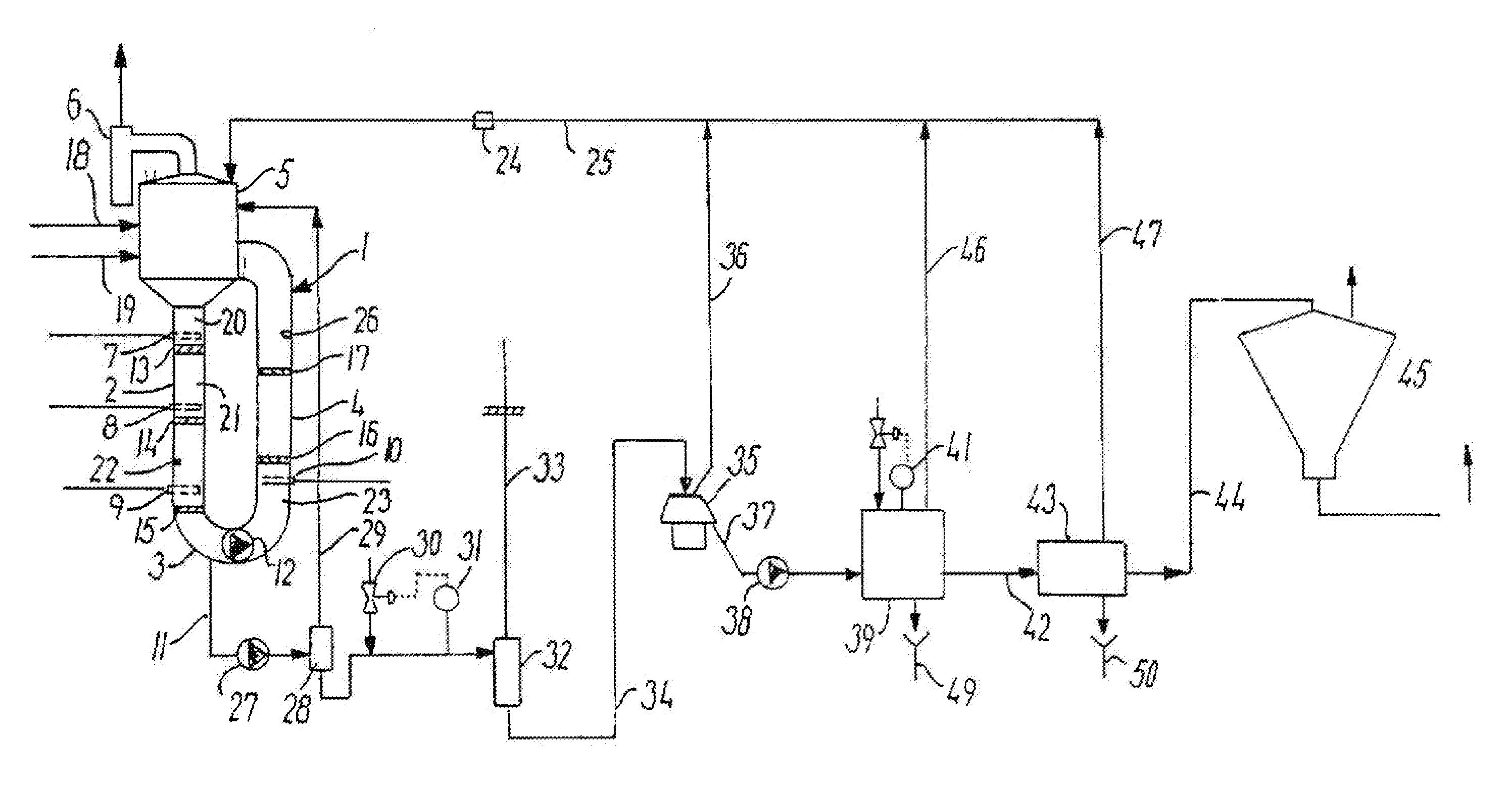
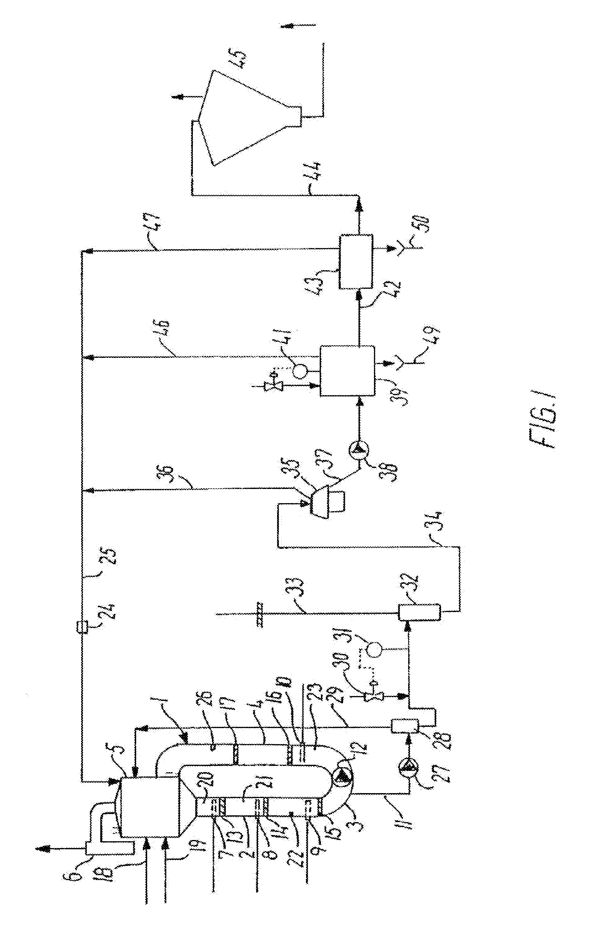
[0110]Single cell protein is produced by a co-fermentation of M. capsulatus with Alcaligenes acidovorans (NCIMB 13287), Aneurinibacillus danicus (NCIMB 13288) and Bacillus firmus (NCIMB 13289) using natural gas as carbon and energy sources and atmospheric air enriched with pure oxygen as an oxygenation source. Ammonia is used as nitrogen source. In addition to theses gaseous substrates, the cultivation of M. capsulatus requires water, phosphate, and several minerals such as magnesium, calcium, potassium, iron, copper, zinc, manganese, nickel, cobalt and molybdenum (added as sulphates, nitrates or chlorides in a mineral mixture). Sodium hydroxide and sulphuric acid are used for pH adjustments. All chemicals are food grade. Phosphate is supplied in the form of phosphoric acid, minerals as sulphates, chlorides or nitrates.

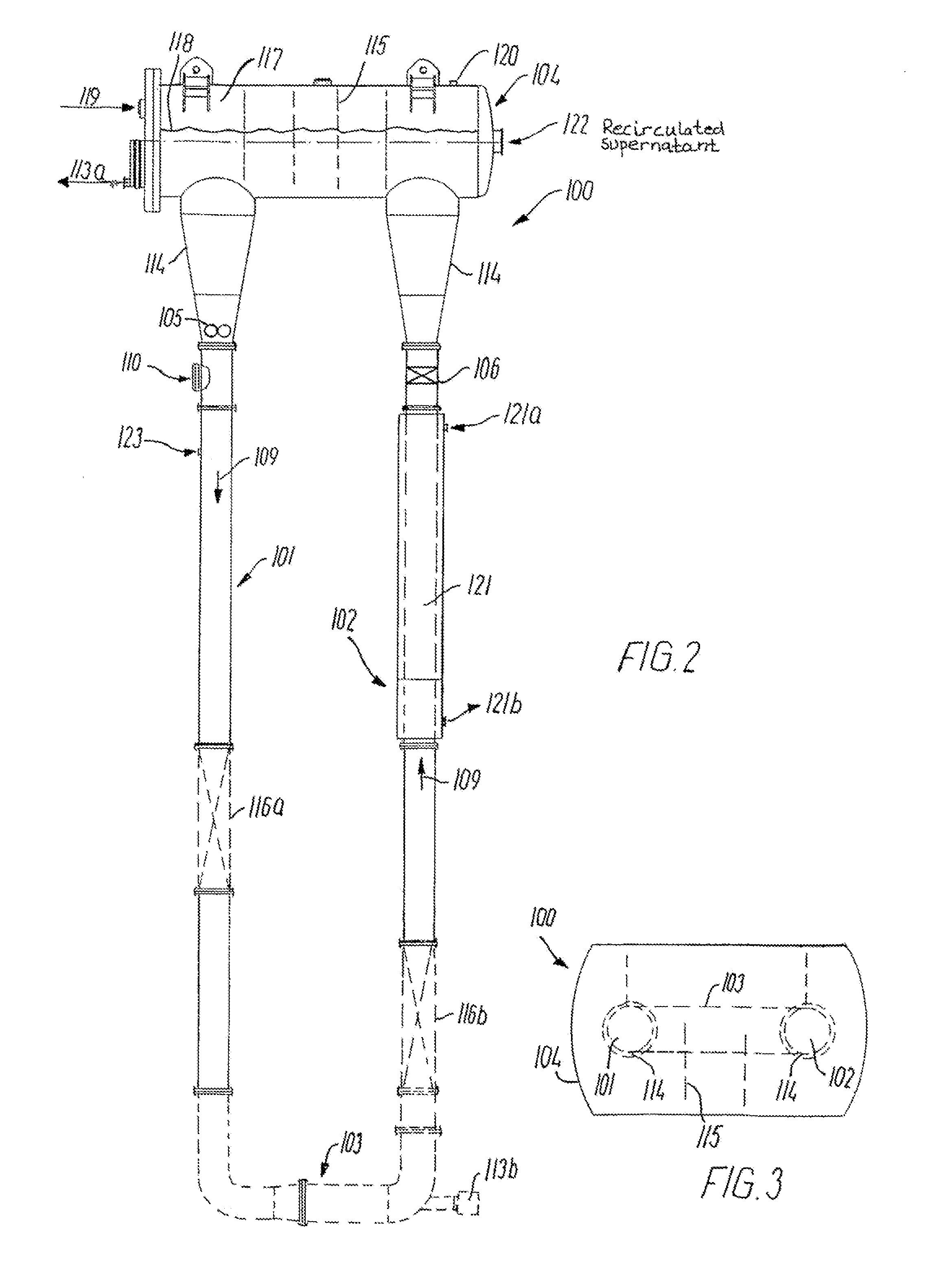
[0111]After cleaning and sterilization, the U-shape fermenter, having a fermentation volume of 10 m3, is filled with water, and the necessary nutrient salts and an in...


PUM

PropertyMeasurementUnit
pressureaaaaaaaaaa
pressureaaaaaaaaaa
pressureaaaaaaaaaa

Abstract

A fermenter and a method of fermentation in a U-shape and / or nozzle U-loop fermenter (100) comprising a U-part having an essentially vertical down-flow part (101), an essentially vertical up-flow part (102) and a substantially horizontal connecting part (103), which connects the lower ends of the down-flow part (101) and the up-flow part (102), a top part (104) which is provided above the U-part and has a diameter which is substantially larger than the diameter of the U-part, means for creating liquid circulation in U-part of the fermenter, and one or more gas injection points (110) for the introduction and dispersion of the gas(ses) into the fermentation liquid. The pressure may be controlled differently in certain zones of the fermenter by pressure controlling devices (105, 106, 108) e.g. by increasing the pressure in certain zones of the fermenter in relation to the pressure in the other zones of the fermenter, or decreasing the pressure in a zone of the fermenter in relation to the pressure in another zone of the fermenter in relation to the pressure in another zone of the fermenter.

Description

FIELD OF THE INVENTION [0001]The present invention relates to a U-shape and / or nozzle U-loop fermenter and to a method of affecting a fermentation process.[0002]More specifically, the invention relates to U-shape and / or nozzle U-loop fermenters and methods for the operation of the same, which are particularly appropriate for production processes with methanotrophic bacteria and similar processes, whereby one or more different gases and other nutrients are to be supplied to the fermentation liquid. The mass transport of gas from the gas phase and into the fermentation liquid is improved in order to obtain an optimally proceeding fermentation process with the highest possible yield of fermentation product in the shortest possible period of time.DEFINITIONS [0003]A fermenter or bioreactor is defined here as a vessel suitable for conducting fermentation or for employing biocatalysts.[0004]A fermentation process is defined as the growth or maintenance of living biocatalysts under aerobic...

Claims


Application Information

Patent Timeline
Patent Type & Authority Applications(United States)
IPC IPC(8): C12P1/04C12M1/04C12P1/00
CPCB01J19/006B01J19/1837C12M41/40C12M29/18B01J2219/00094
Inventor LARSEN
Owner UNIBIO AS
Why Eureka
Try Eureka