Ring cathode for use in a magnetron sputtering device

a ring cathode and magnetron technology, applied in the direction of vacuum evaporation coating, electrolysis components, coatings, etc., can solve the problems of reducing the mean-free path, increasing the probability of gas atom-electron collision, and reducing the sputtering rate. achieve the effect of improving the uniformity of planets, reducing the degree of mechanical deviation in vertical and horizontal positioning, and increasing the uniformity of coatings

Active Publication Date: 2011-10-20
VIAVI SOLUTIONS INC
View PDF0 Cites 11 Cited by
  • Summary
  • Abstract
  • Description
  • Claims
  • Application Information

AI Technical Summary

Benefits of technology

[0041]Advantageously, the present invention increases coating uniformity in both runoff and planet to planet results over the prior art. Tolerance to mechanical deviation in vertical and horizontal positioning is significantly relaxed. Thus with close mechanical control significant improvement in planet to pla

Problems solved by technology

This results in an increase in the gas atom-electron collision probability, thereby leading to a much higher sputtering rate than that obtained without the use of magnetic confinement.
High pressure has the disadvantage that the mean-free path is greatly reduced, which causes extensive gas scatter.
This results in hazy coatings.
But over time the masks typically accumulate large amounts of coating material.
Once the material on the mask reaches a critical thickness it may flake off and contribute to particles that compromise the coating quality.
Furthermore, as masks become coated, they gradually change their shape, which continuously alters the coating distribution.
If the coating is an electrically insulating material, such as a metal oxide, the build up of the material on other parts of the sputtering apparatus can cause problems.
In particular, the b

Method used


Image

  • Ring cathode for use in a magnetron sputtering device
  • Ring cathode for use in a magnetron sputtering device
  • Ring cathode for use in a magnetron sputtering device

Examples


Embodiment Construction

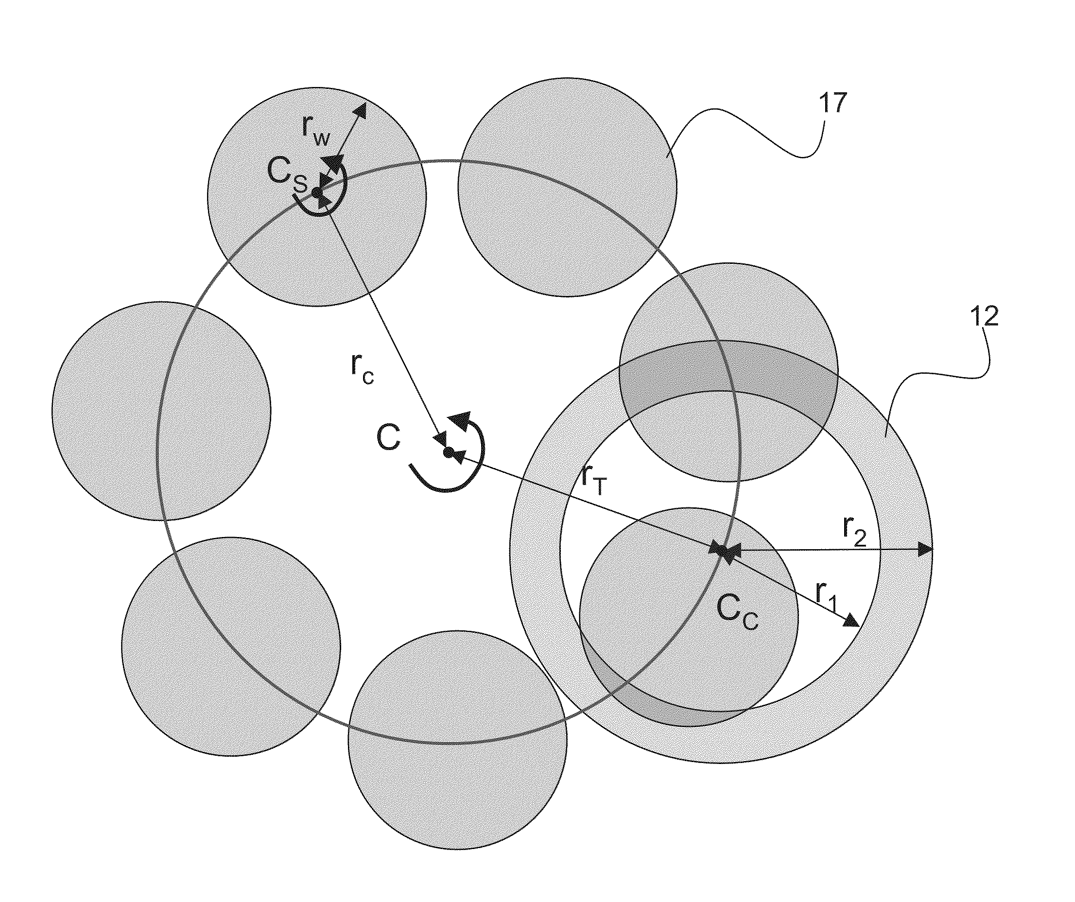
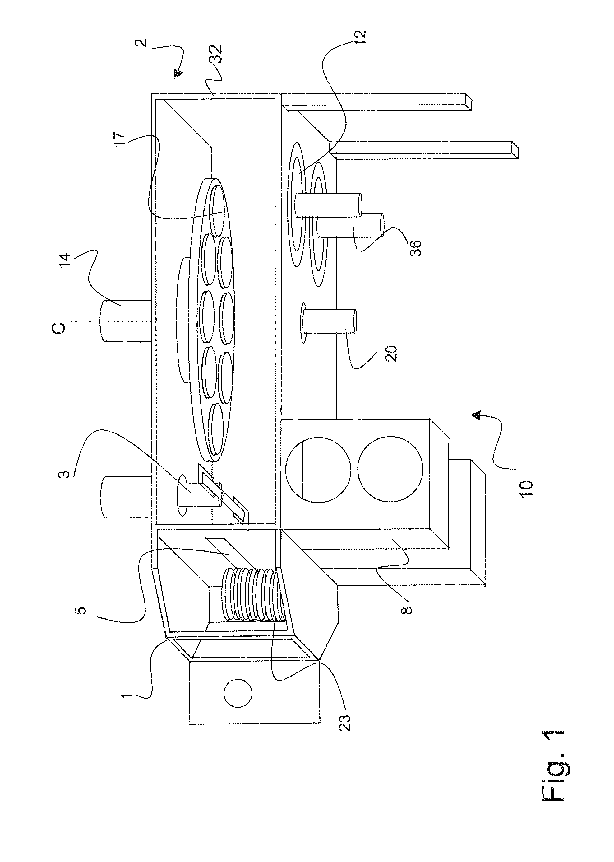
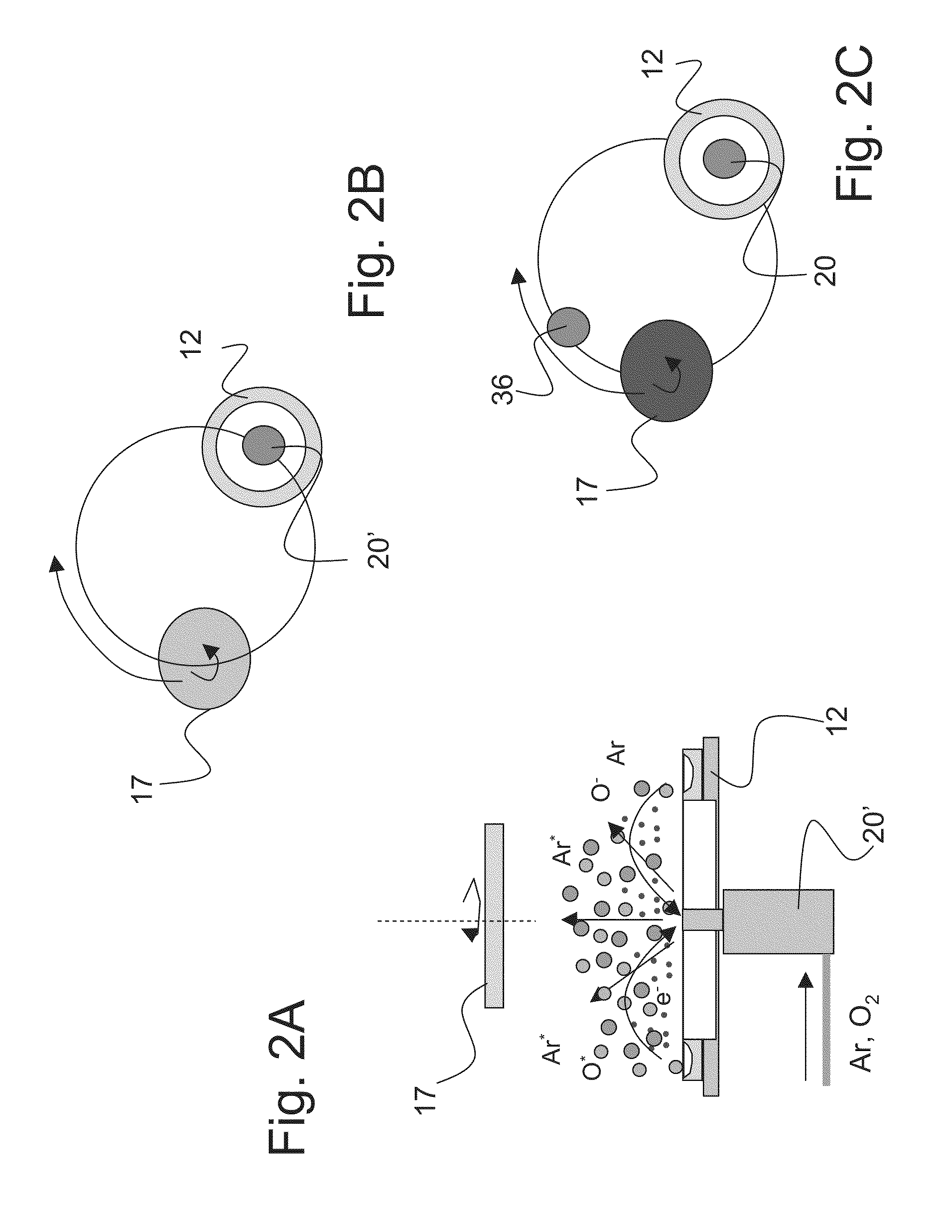
[0062]An isometric view of the coating chamber 2 of the magnetron sputter coating device 10 is shown in FIG. 1. Pumps 8 evacuate the coating chamber 2 for operation under vacuum conditions, understood to mean where the pressure is below atmospheric pressure. The chamber walls 32 are grounded and isolated from the positively charged anode 20 and the negatively charged cathode 12. A planetary drive 14, seen in more detail in FIGS. 3A and 3B, comprises a carrier 16 or rack rotatable about a central rotational axis C, with a plurality of eg. seven or eight, planets 17 supported radially about the central rotational axis C. A carrier radius rC is defined between the central axis C and the planet axis Cs. A ring shaped cathode 12, in this embodiment two cathodes 12, are shown each having a central axis Cc that is offset from the central axis C of the planetary drive 14. Anode 20, in the form of a vessel with an opening in communication with the coating chamber 2, is shielded from coating ...


PUM

PropertyMeasurementUnit
Massaaaaaaaaaa
Pressureaaaaaaaaaa
Diameteraaaaaaaaaa

Abstract

The present invention relates to a magnetron sputtering device including a large ring cathode having a defined inner radius. The position of the ring cathode is offset in relation to a center point of a planetary drive system. An anode or reactive gas source may be located within the inner radius of the ring cathode. Lower defect rates are obtained through the lower power density at the cathode which suppresses arcing, while runoff is minimized by the cathode to planet geometry without the use of a mask.

Description

CROSS-REFERENCE TO RELATED APPLICATIONS[0001]This application claims priority from U.S. provisional application No. 61 / 325,162 filed 16 Apr. 2010, which is incorporated herein by reference for all purposes.FIELD OF THE INVENTION[0002]This invention relates generally to a magnetron sputtering device for depositing materials onto substrates in which the deposited films have a predictive thickness distribution with low defect levels. More particularly the invention relates to a ring cathode for use in a magnetron sputtering device and a magnetron sputtering device incorporating the same.BACKGROUND OF THE INVENTION[0003]Sputter coating is a widely used technique for depositing a thin film of material on a substrate. In a sputtering deposition process ions are usually created by collisions between gas atoms and electrons in a glow discharge. The ions are accelerated into the target of coating material at the cathode by an electric field causing atoms of the target material to be ejected ...

Claims


Application Information

Patent Timeline
IPC IPC(8): C23C14/35
CPCH01J37/3405H01J37/3423C23C14/0036C23C14/3407C23C14/35H01L21/68771H01J37/3417H01J37/3438H01J37/347H01L21/68764C23C14/505
Inventor OCKENFUSS, GEORG J.
Owner VIAVI SOLUTIONS INC
Why Eureka
Try Eureka