Energy storage device and manufacturing method thereof

a technology of energy storage and manufacturing method, which is applied in the direction of cell components, final product manufacturing, sustainable manufacturing/processing, etc., can solve the problem of difficult to obtain a discharge capacity as high as the theoretical capacity in practice, and achieve the effect of high discharge capacity

Active Publication Date: 2011-12-01
SEMICON ENERGY LAB CO LTD
View PDF6 Cites 18 Cited by
  • Summary
  • Abstract
  • Description
  • Claims
  • Application Information

AI Technical Summary

Benefits of technology

[0009]In view of the above, an object of one embodiment of the present invention is to provide an energy storage device whose discharge capacity can be improved and a method for manufacturing the energy storage device.

Problems solved by technology

However, even when silicon is used as a negative electrode active material, it is difficult to obtain a discharge capacity as high as the theoretical capacity in practice.

Method used


Image

  • Energy storage device and manufacturing method thereof
  • Energy storage device and manufacturing method thereof
  • Energy storage device and manufacturing method thereof

Examples


embodiment 1

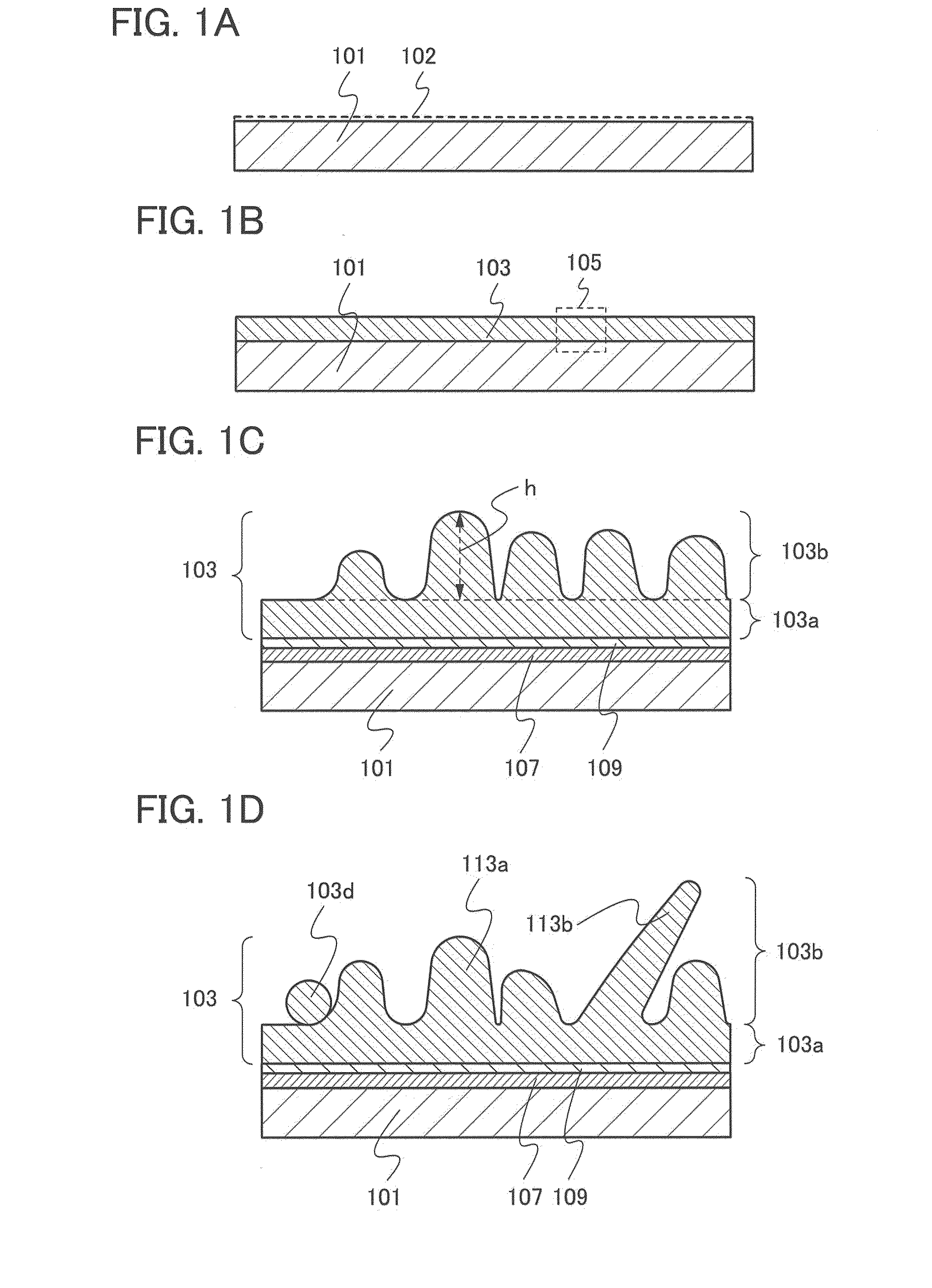
[0024]In this embodiment, an electrode of an energy storage device which is one embodiment of the present invention and a manufacturing method thereof will be described with reference to FIGS. 1A to 1D and FIG. 2.

[0025]As illustrated in FIG. 1A, over a current collector 101, a metal element is dispersed by a coating method typified by spin coating, whereby a region 102 in which the metal element is dispersed is formed.

[0026]The current collector 101 functions as a current collector of an electrode. Thus, the current collector 101 is formed using a conductive material having a foil shape, a plate shape, or a net shape. For example, the current collector 101 can be formed using a metal element with high conductivity typified by platinum, aluminum, copper, or titanium. Alternatively, the current collector 101 may be formed using an aluminum alloy to which an element which improves heat resistance, such as silicon, titanium, neodymium, scandium, or molybdenum, is added. Further alternat...

example

[0050]In this example, the growth of silicon whiskers when a silicon layer is formed by LPCVD over the region in which a metal element is dispersed is described.

[0051]The description of samples used in this example is made. A chemical solution including a metal element (nickel acetate) was applied to a glass substrate, whereby the metal element was dispersed. At that time, as the concentration of nickel acetate, two conditions of 100 ppm and 1000 ppm were adopted.

[0052]Then, a crystalline silicon layer was formed by LPCVD over the region in which the metal element was dispersed. The film formation of a crystalline silicon layer by LPCVD was performed as follows: silane was introduced as a source gas into a reaction chamber with a flow rate of 300 sccm, the pressure of the reaction chamber was 20 Pa, and the temperature of the reaction chamber was 600° C. Further, the deposition time was 2 hours and 15 minutes.

[0053]FIGS. 8A and 8B show scanning-electron-microscope (SEM) images of th...

embodiment 2

[0058]In this embodiment, a structure of an energy storage device will be described with reference to FIGS. 3A and 3B.

[0059]First, a structure of a secondary battery that is one example of an energy storage device is described. Among secondary batteries, a lithium ion battery formed using a lithium-containing metal oxide such as LiCoO2 has a high capacity and high safety. Here, the structure of the lithium ion battery that is a typical example of a secondary battery is described.

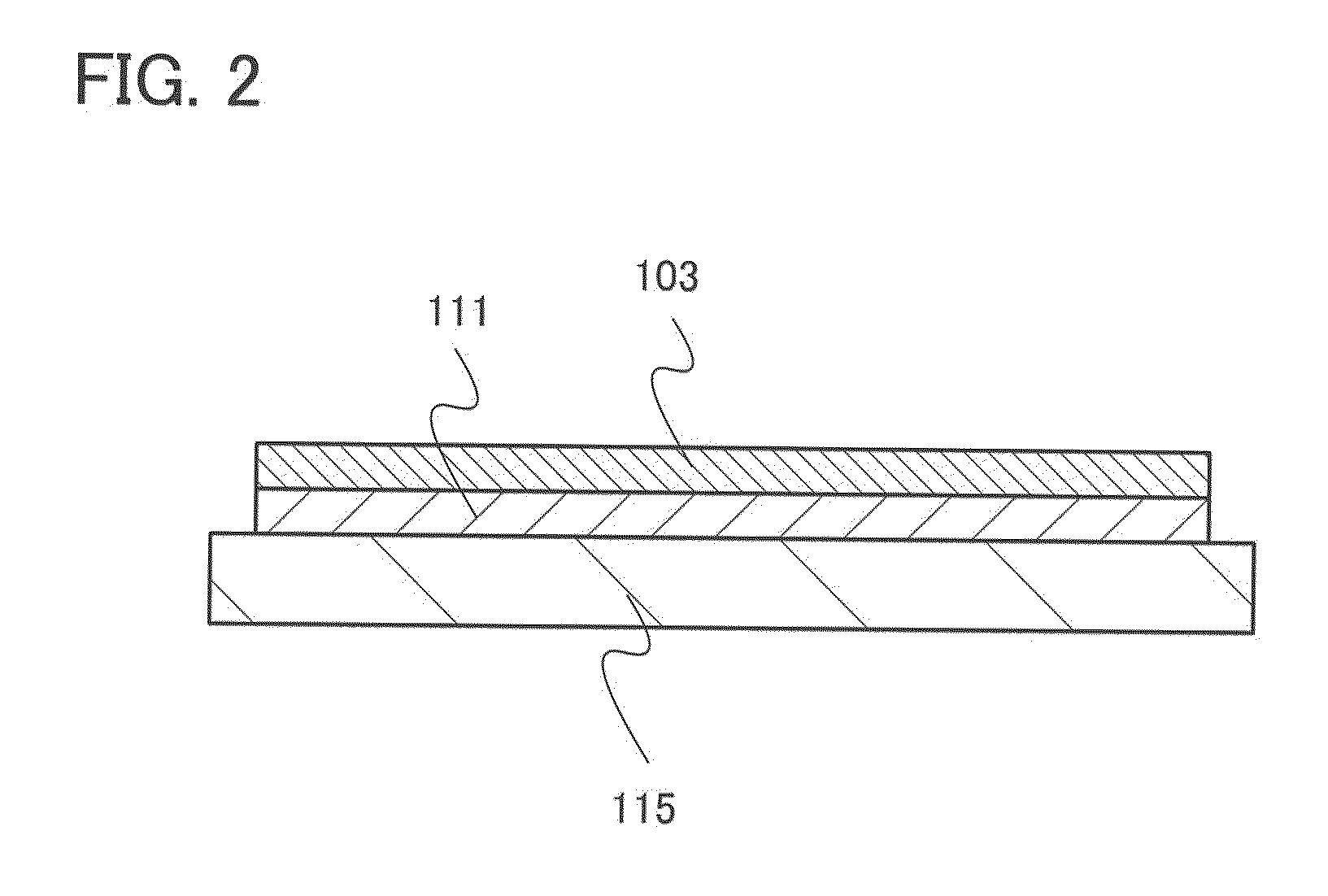
[0060]FIG. 3A is a plan view of an energy storage device 151, and FIG. 3B is a cross-sectional view taken along dot-dashed line A-B in FIG. 3A.

[0061]The energy storage device 151 illustrated in FIG. 3A includes an energy storage cell 155 in an exterior member 153. The energy storage device 151 further includes terminal portions 157 and 159 which are connected to the storage cell 155. For the exterior member 153, a laminate film, a polymer film, a metal film, a metal case, a plastic case, or the like can be u...


PUM

PropertyMeasurementUnit
temperatureaaaaaaaaaa

Abstract

An energy storage device whose discharge capacity can be improved and a method for manufacturing the energy storage device are provided. A method for manufacturing an energy storage device, in which a metal element is dispersed over a current collector, and a crystalline silicon layer including a whisker is formed as an active material layer over the surface of the current collector on which the metal element is dispersed by low pressure chemical vapor deposition (LPCVD) in which heating is performed using a deposition gas containing silicon. Having whiskers in the active material layer as described above, the surface area of the active material layer is increased; thus, the discharge capacity of the energy storage device can be increased.

Description

BACKGROUND OF THE INVENTION[0001]1. Field of the Invention[0002]The present invention relates to an energy storage device (a power storage device) and a manufacturing method thereof.[0003]Note that the energy storage device indicates all elements and devices which have a function of storing energy.[0004]2. Description of the Related Art[0005]In recent years, energy storage devices such as lithium-ion secondary batteries, lithium-ion capacitors, and air cells have been developed.[0006]The electrode of an energy storage device is formed by forming an active material over a surface of a current collector. As the active material, a material which can store and release ions functioning as carriers, such as carbon or silicon, is used. Specifically, silicon or phosphorus-doped silicon has higher theoretical capacity than carbon; thus, it is preferable to use the material as an active material in terms of increased capacity of the energy storage device (e.g., Patent Document 1).REFERENCE[00...

Claims


Application Information

Patent Timeline
Patent Type & Authority Applications(United States)
IPC IPC(8): H01M6/00H01M4/1395H01M4/70H01M4/74
CPCH01M4/0428Y10T29/49108Y02E60/122H01M4/1395Y02E60/10C23C16/06H01G9/04H01M4/04H01M4/66H01G11/24H01G11/26H01G11/28H01M4/0404H01M4/242H01M4/386H01M4/52H01M4/521H01M4/523H01M4/525Y02P70/50
Inventor YAMAZAKI, SHUNPEI
Owner SEMICON ENERGY LAB CO LTD
Why Eureka
Try Eureka