[0025]According to the first form of the present invention, because, in said synthesis step, the carrier gas at or above said synthetic temperature is supplied in the periphery or its front and rear stages of said raw material gas that is placed in contact with the surface of said catalyst substrate,
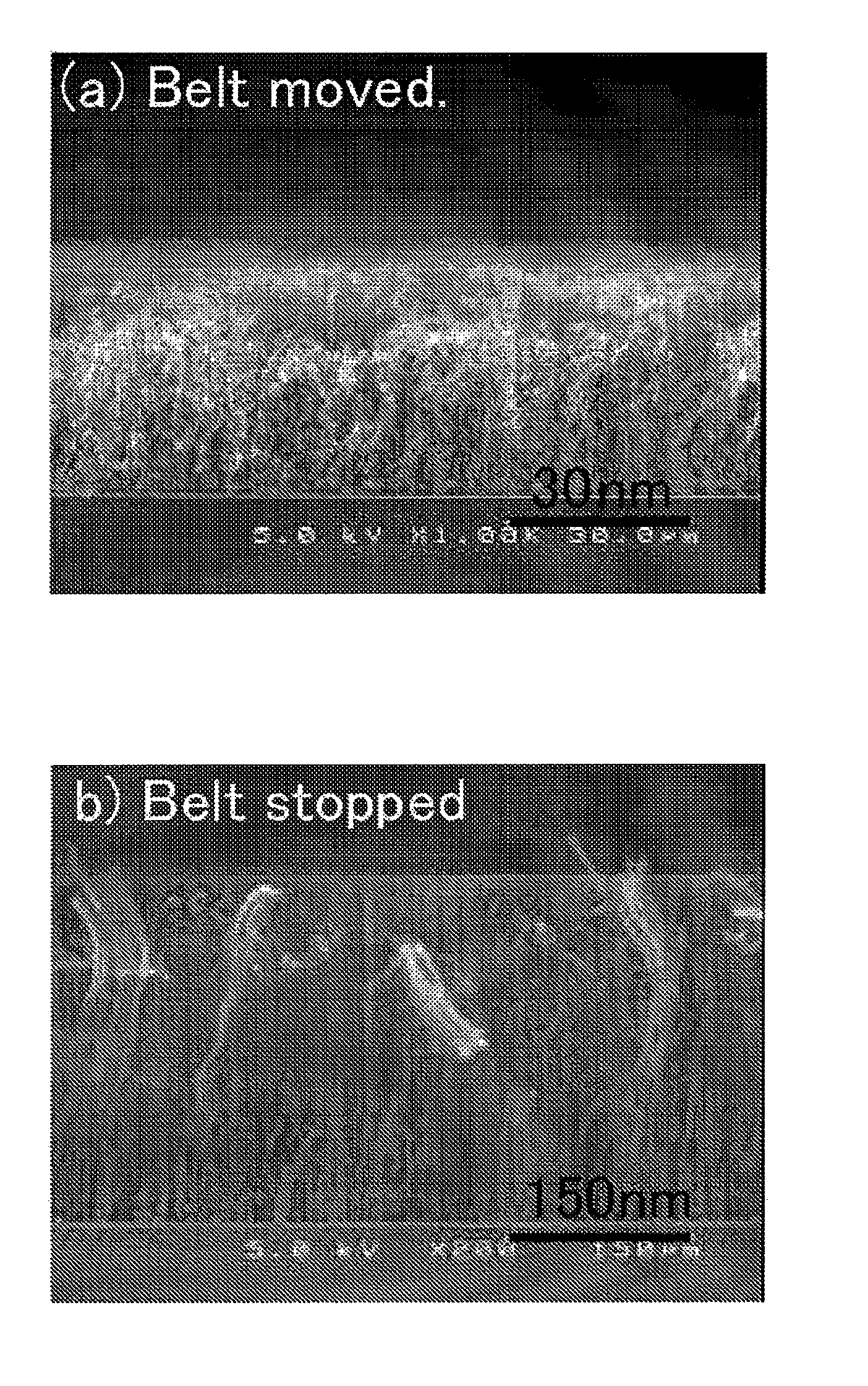
diffusion of the raw material gas and subsequent contact with the catalyst substrate during its temperature increase can be restrained. As described previously, it had been confirmed that the orientation of synthesized oriented carbon nanotubes decreases when raw material gas comes into contact with the catalyst substrate whose temperature is increasing. According to the first form, by the suppression of
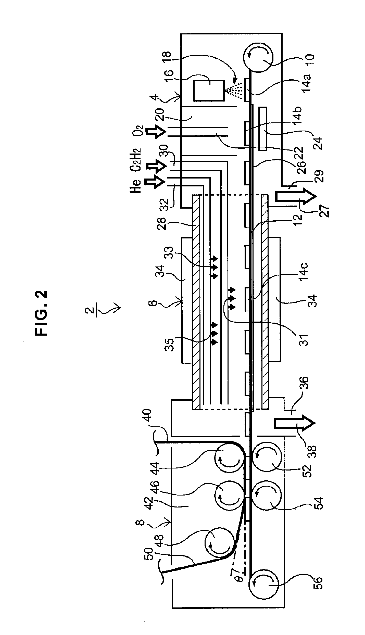
diffusion of the raw material gas through supplying the carrier gas at the periphery of said raw material gas or its front and rear stages, contact of the raw material gas, to a catalyst substrate whose temperature is increasing and has not reached the synthesis temperature, can be prevented. Therefore, oriented carbon nanotubes whose orientation is high (subsequently referred to as “highly oriented carbon nanotubes”) can be synthesized. Also, said carrier gas, at least until it contacts the surface of the catalyst substrate, is heated together with the raw material gas to the synthesis temperature or above, and it can suppress a contact to the catalyst substrate to the raw material gas that has diffused and cooled, not reaching the synthesis temperature. Said carrier gas may be supplied at the front and rear stages of the raw material gas supplied on the surface of the catalyst substrate, in the way that the raw material gas is bracketed. If the carrier gas is supplied so that it completely surrounds the periphery of said raw material gas, a more stable synthesis concentration region can be formed.
[0026]In said
coating and
drying step, after forming the catalyst layer on the surface of the substrate by
coating with a catalyst solution and
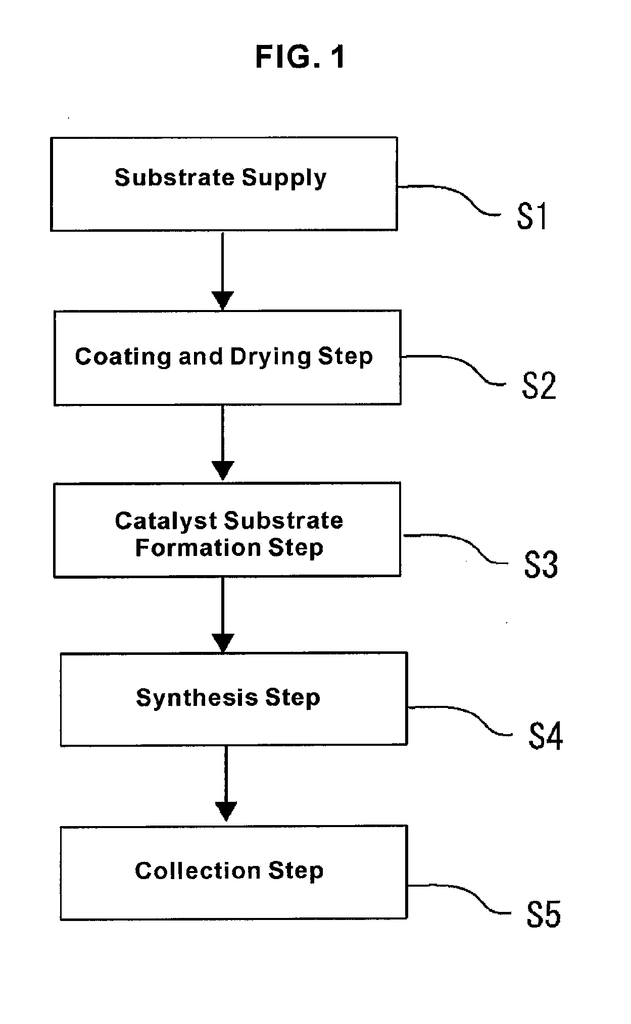
drying, the catalyst substrate that has a catalyst particle layer on said catalyst surface is formed during said catalyst substrate formation step by heating said catalyst layer. Therefore, a catalyst particle layer whose particle
diameter is relatively uniform can be formed. Said catalyst solution is a liquid in which a
metal compound that includes a catalyst
metal is dissolved or dispersed, and by coating with this liquid and drying, an extremely thin catalyst layer can be formed on the
substrate surface. For the coating of catalyst solution, a
spray method and an inkjet methods, among others, are used, and the catalyst solution is sprayed or printed. By controlling, among others, the flow rate of the gas for spraying, the flow rate of the film formation liquid, and the
nozzle shapes, the film thickness of the coating film can be controlled. Also, even when the substrate surface has an uneven configuration, a coating film can be adhered. By spray print, an arbitrary pattern can be printed on a substrate surface by using a
mask, for example. Therefore, it is preferable to use a catalyst solution in which said
metal compound is dispersed or dissolved in a
solvent with an ample wettability with said substrate. Furthermore, by heating the catalyst layer and granulating it during said catalyst substrate formation step, a catalyst particle layer having a small, and at the same time, uniform particle size can be formed. Therefore, through the synergic effect with the synthetic condition of the first form, oriented carbon nanotubes with high orientation having even more uniform
diameter can be synthesized. Also, said catalyst metal is a
transition metal such as iron (Fe),
cobalt (Co),
nickel (Ni),
molybdenum (Mo),
platinum (Pt) and such, and iron,
cobalt,
nickel are particularly preferable. Also, it may be a mixture of one kind or two or more kinds among these metals. Furthermore, said metal compound is an organometallic salt or an inorganic metal salt. Among the organometallic salts, for example, acetates, oxalates, citrates and such are included. Among the inorganic
metal salts, nitrates, oxo acid salts and such are included. Also, said metal compound may be a mixture of one kind or two or more kinds of these
metal salts.
[0027]Furthermore, according to the first form of the present invention, because it includes the collection step for collecting said oriented nanotubes, the synthesized oriented carbon nanotubes can be collected as a product. For said substrate, one can use a continuous body or aligned substrates in which one or more substrates are aligned. A catalyst solution is coated on the surface of the continuous body or the aligned substrates, and by drying this, a catalyst layer is formed. As described earlier, in said catalyst substrate formation step, said catalyst layer is heated. The catalyst particle layer is formed and becomes the catalyst substrate. In the present invention, because substrates are supplied continuously or intermittently, catalyst substrates can be formed and supplied sequentially or continuously, so that oriented carbon nanotubes are synthesized continuously or intermittently to be collected. At the time of collection, the synthesized oriented carbon nanotubes can be detached and collected, or they may be collected in a state in which they are bonded to the catalyst substrate. Also, a thread-like
carbon nanotube aggregate can be formed by pulling a part of the packed oriented carbon nanotubes, and by
spinning this, the oriented carbon nanotubes can be collected. Also, for a substrate comprising the continuous body or aligned in the aligned substrates, it is preferably a
ceramic material, an inorganic
nonmetal, or an inorganic
nonmetal compound among others, that is resistant at or above said synthesis temperature. For example, a
quartz plate, a
silicon substrate, a
silicon wafer, a
rock crystal plate, a fused silica plate, a
sapphire plate, or a stainless steel plate, among others, can be used.
[0028]According to the second form of the present invention, the synthesis concentration region over said catalyst substrate, in which the concentration of said raw material gas has been set to be equal to or higher than the predetermined concentration for growing oriented carbon nanotubes, is made to be smaller than the synthesis temperature region over said catalyst substrate that has been set to be equal to or higher than said synthesis temperature. Because of this, highly oriented carbon nanotubes can be synthesized more reliably. Present inventor, as the result of an intensive study, came to complete the method for synthesizing highly oriented carbon nanotubes by supplying a raw material gas, set at or above said synthesis temperature, in short time and at a suitable concentration.
[0029]Said synthesis concentration region is: (1) a region over a catalyst substrate surface on which the concentration of the raw material gas has reached the concentration in which synthesis of oriented carbon nanotubes has become possible (also, simply referred to as “synthesis concentration”), (2) a region included in the concentration distribution, or the range of its
full width at half maximum, over the catalyst substrate surface, or (3) a region satisfying both of those conditions. If the raw material
gas concentration over the catalyst substrate surface increases steeply, each of the synthesis concentration regions that fulfill the condition in said (1)-(3) indicates approximately one same region on the catalyst substrate surface. Also, the synthesis temperature range indicates a region over the catalyst substrate surface that has reached the temperature in which oriented carbon nanotubes are synthesized from the raw material gas at or above said synthesis concentration (also, referred to simply as “synthesis temperature”).
[0030]According to the second form of the present invention, the synthesis concentration region in the catalyst substrate is set smaller in area than said synthesis temperature region. Because of this, the raw material gas that is at or above the synthesis concentration, and in contact with the catalyst substrate, has approximately reached said synthesis temperature. Therefore, the raw material gas at or above the synthesis concentration does not come into contact during a temperature rise. Therefore, on the catalyst substrate, a region is maintained satisfying the synthetic condition concerning the concentration and temperature of the raw material gas. Because of this, the raw material gas comes into contact with a new catalyst substrate surface after said catalyst substrate is moved, and oriented carbon nanotubes are synthesized. That is to say, highly oriented carbon nanotubes can be stably synthesized continuously or intermittently during said synthesis step, by supplying heated raw material gas to a catalyst substrate. Also, in said synthesis concentration region, it is preferable that the raw material
gas concentration increases steeply from outside the region. This way, it becomes easy to form a region of raw material gas uniformly satisfying the synthetic condition concerning the concentration and temperature, and highly oriented
carbon nanotube can be synthesized more reliably.

