Metal oxide ultrafine fiber-based composite separator with heat resistance and secondary battery using same
- Summary
- Abstract
- Description
- Claims
- Application Information
AI Technical Summary
Benefits of technology
Problems solved by technology
Method used
Image

Examples
example 1-1
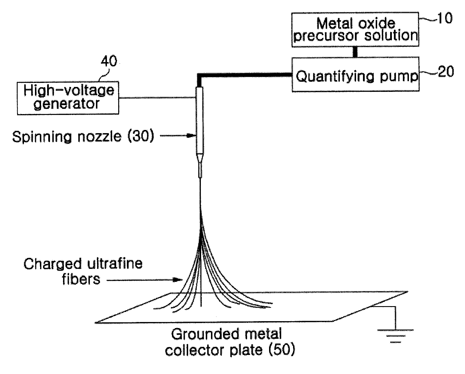
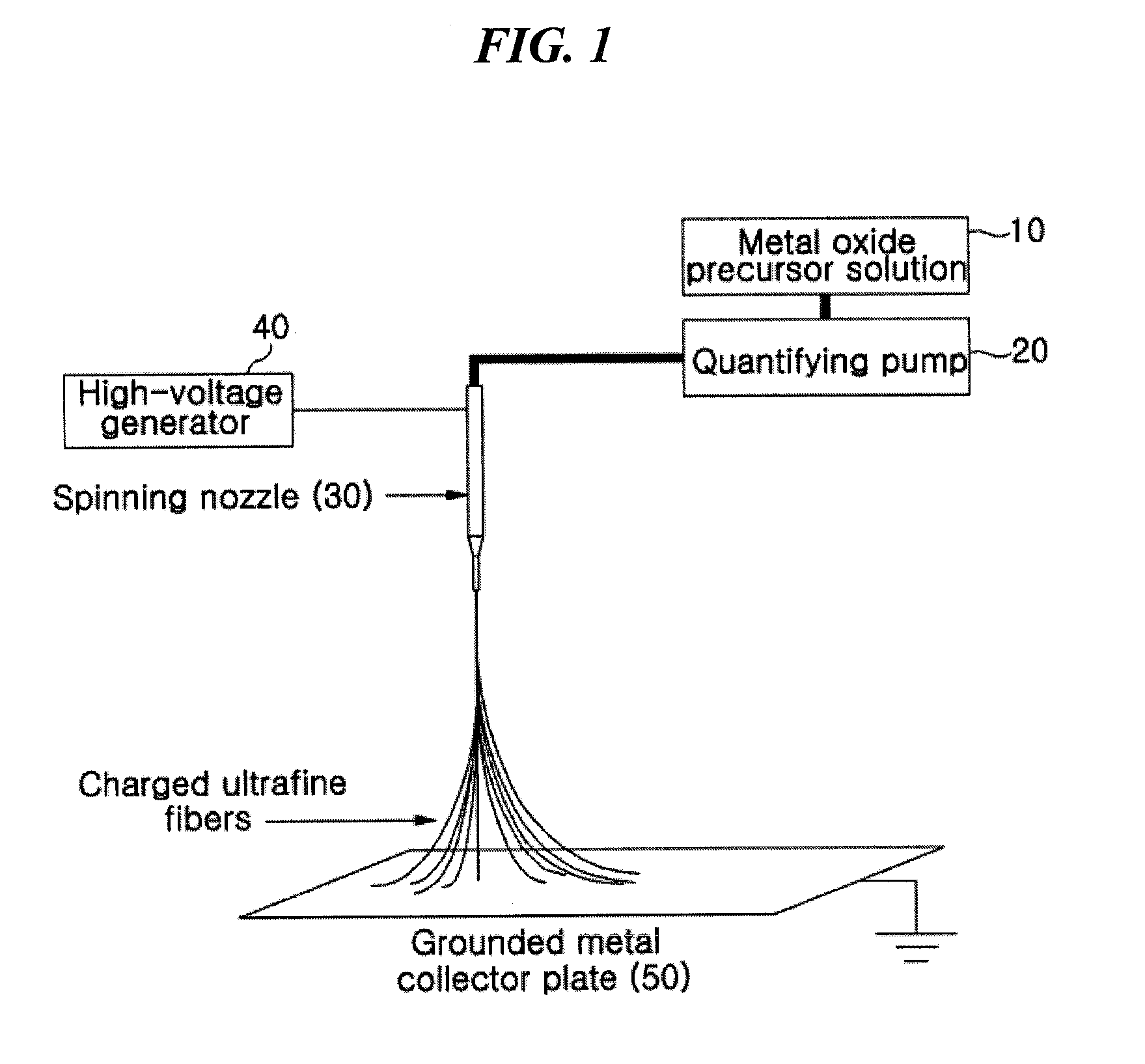
[0078]A mixture solution comprising 20.8 g of tetraethoxyorthosilicate (TEOS), 9.2 g of ethylalcohol, 3.5 g of water and 0.1 g of an aqueous hydrochloric acid solution was stirred at about 70° C. for about 3 hours, thus preparing a TEOS sol-gel solution, which was then electrospun using a 30G spinning nozzle at a delivery rate of 20 μl / min under a high-voltage electric field of 20 kV by means of the electrospinning device of FIG. 1, thus manufacturing silica ultrafine fibrous porous body. The porous body was sintered at about 400° C. to obtain a porous body comprising silica ultrafine fibers having an average diameter of 680 nm. The TEM image of the silica ultrafine fibers is shown in (a) of FIG. 4.
example 1-2
[0079]7 g of aluminum isopropoxide, 40 ml of ethylalcohol, ml of water and 25 ml of aqueous hydrochloric acid solution were mixed and stirred thus preparing an aluminum isopropoxide sol-gel solution. This solution was added with a solution of 5 ml of ethylalcohol and 1.5 g of PVP and stirred at about 70° C. for 2 hours thus preparing a mixture solution. This solution was electrospun using a 24G spinning nozzle under a high-voltage electric field of 15.5 kV at a delivery rate of 30 μl / min by means of the electrospinning device of FIG. 1, thus manufacturing an alumina / PVP ultrafine fibrous porous body. The porous body was sintered at about 500° C. to remove PVP therefrom, to obtain a porous body comprising alumina ultrafine fibers having an average diameter of 600 nm. The TEM image of the alumina ultrafine fibers is shown in (b) of FIG. 4.
example 1-3
[0080]The ultrafine fibrous silica porous body of Example 1-1 was impregnated in a DMF solution having PVdF and polyetherimide (1:1 weight ratio) dissolved in a 5% weight ratio therein, dried, and then heat compressed at about 150° C., thus manufacturing a composite separator having a porosity of 65%. The TEM image of the separator is shown in (c) of FIG. 4. This separator was stored in an oven at 200° C. for about 1 hour and then the heat shrinkage rate thereof was measured to be about 4.3%. The results of evaluating heat resistance properties using TMA showed that the separator did not break down due to melting up to about 300° C. and thus exhibited high heat stability.
PUM
| Property | Measurement | Unit |
|---|---|---|
| Temperature | aaaaa | aaaaa |
| Temperature | aaaaa | aaaaa |
| Temperature | aaaaa | aaaaa |
Abstract
Description
Claims
Application Information
 - R&D
- Intellectual Property
- Life Sciences
- Materials
- Tech Scout
- Unparalleled Data Quality
- Higher Quality Content
- 60% Fewer Hallucinations
Browse by: Latest US Patents, China's latest patents, Technical Efficacy Thesaurus, Application Domain, Technology Topic, Popular Technical Reports.
© 2025 PatSnap. All rights reserved.Legal|Privacy policy|Modern Slavery Act Transparency Statement|Sitemap|About US| Contact US: help@patsnap.com