Silicon Single Crystal Doped with Gallium, Indium, or Aluminum
- Summary
- Abstract
- Description
- Claims
- Application Information
AI Technical Summary
Benefits of technology
Problems solved by technology
Method used
Image
Examples
example 1
[0061]In FIG. 15, the radial resistivity of a crystal ingot (sample 1) made in accordance with the preferred embodiment of this invention is shown. The crystal was the third ingot grown in a CCZ run wherein elemental gallium was added in the initial charge and within the growth zone 36 via a cup-like vessel formed on seed crystal 38 between ingots in an amount determined in accordance with the doping model. No additional dopant was added into the melt zone 34 during crystal growth or between ingot growth. As can be seen, the radial resistivity is relatively uniform throughout the length of the crystal. It is noted that the resistivity measurements for all examples were taken post thermal donor kill or TDK, a heat treatment that is applied to silicon wafers so that their measured resistivity better reflects actual working resistivities for use in solar cells. FIG. 16 shows the resistivity of the crystal sample 1 along the axial length of sample 1.
example 2
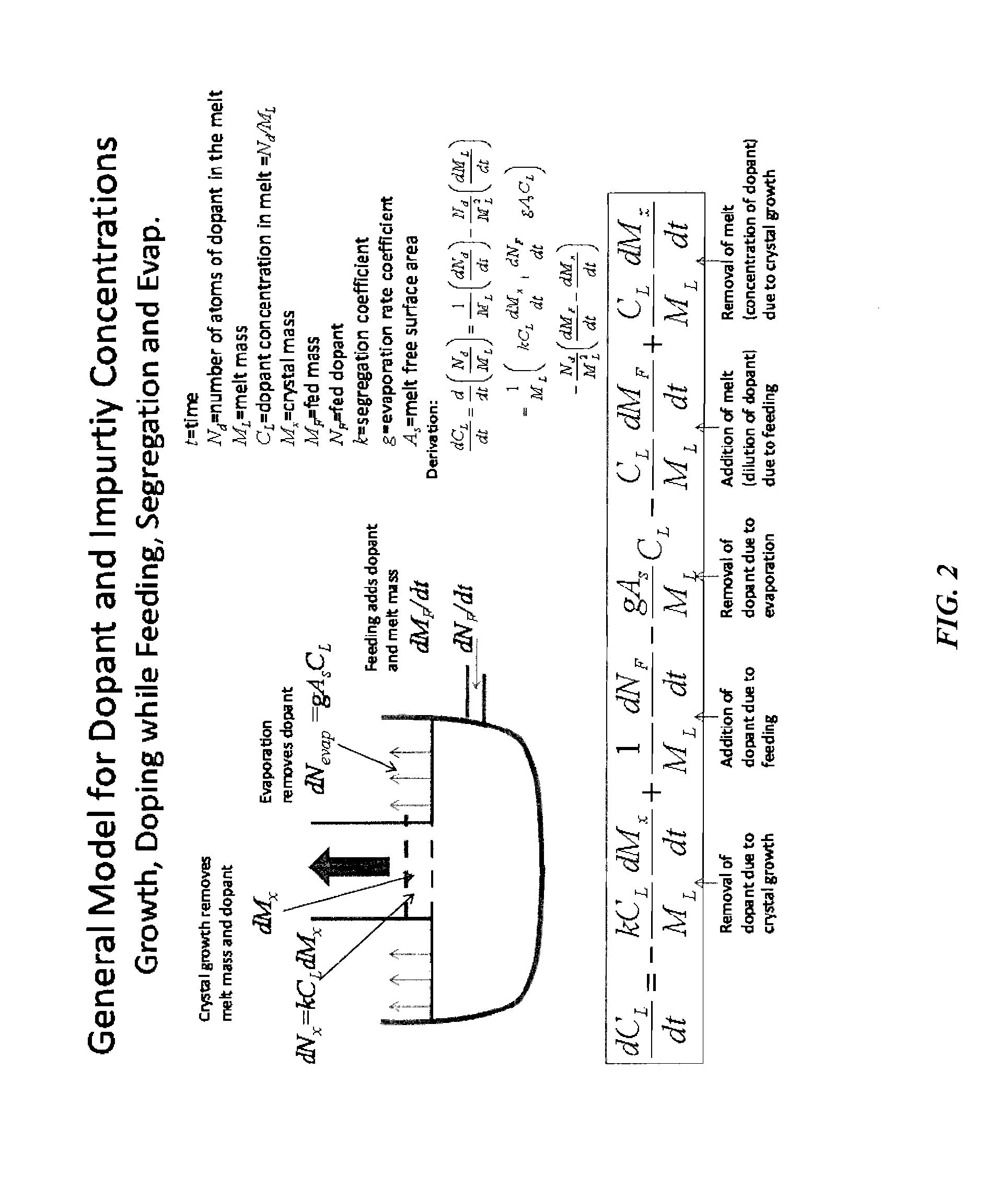
[0062]FIG. 17 shows the actual amount of gallium dopant added to three crystal ingots produced using the CCZ process and in accordance with the doping model of the present invention. The amount of dopant added inter-ingot was determined in accordance with the doping model and based upon the desired resistivity of the ingot. No additional dopant was added in the outer chamber during or between ingot growth. FIG. 17 shows the anticipated resistivity in accordance with the model and the actual measured resistivity.
[0063]FIG. 18 shows the actual resistivity of the three crystals grown and shown in preceding FIG. 17 along the length of each crystal. FIG. 19 shows the axial resistivity of crystals grown with both gallium doping in the inner growth chamber between ingot growth and additional dopant added during growth to the outer chamber by means of dopant containers, in comparison to a crystal with doping only to the inner growth chamber between ingot growth. It is noted that the resisti...
example 3
[0064]For this experiment, 40 solar cells were made from 125 mm×125 mm pseudo-square wafers. Next to a control group of 10 wafers for the optimization, 15 cells were made of boron doped substrates using a CCZ process with addition of dopant to the inner growth chamber between ingot growth and addition to the outer growth chamber during growth, and 15 cells were made of gallium doped substrates with addition of dopant to the inner growth chamber between ingot growth. The resistivities of the wafers are given in Table I. Note that Group 2 has approximately double the dopant concentration compared to Group 1.
TABLE IResistivities of the used substrates.Base dopingResistivityGroup 1p-type, Boron2.1 Ω cmGroup 2p-type, Gallium1.0 Ω cm
[0065]With reference to FIG. 20, the solar cell process used in this experiment was a selective emitter approach adhering closely to standards used in the industry. The cells underwent an alkaline texturing before POCl3 emitter diffusion to about 30 Ω / sq and p...
PUM
 Abstract
Description
Claims
Application Information
 - R&D
- Intellectual Property
- Life Sciences
- Materials
- Tech Scout
- Unparalleled Data Quality
- Higher Quality Content
- 60% Fewer Hallucinations
Browse by: Latest US Patents, China's latest patents, Technical Efficacy Thesaurus, Application Domain, Technology Topic, Popular Technical Reports.
© 2025 PatSnap. All rights reserved.Legal|Privacy policy|Modern Slavery Act Transparency Statement|Sitemap|About US| Contact US: help@patsnap.com


