
Aerosol Collection Apparatus and Methods

Inactive Publication Date: 2012-07-12
ENERTECHNIX
View PDF0 Cites 72 Cited by
  • Summary
  • Abstract
  • Description
  • Claims
  • Application Information

AI Technical Summary

Benefits of technology

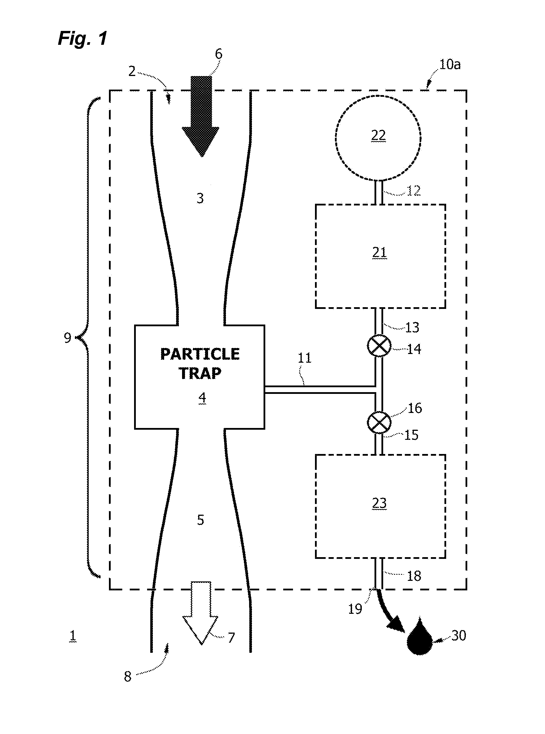
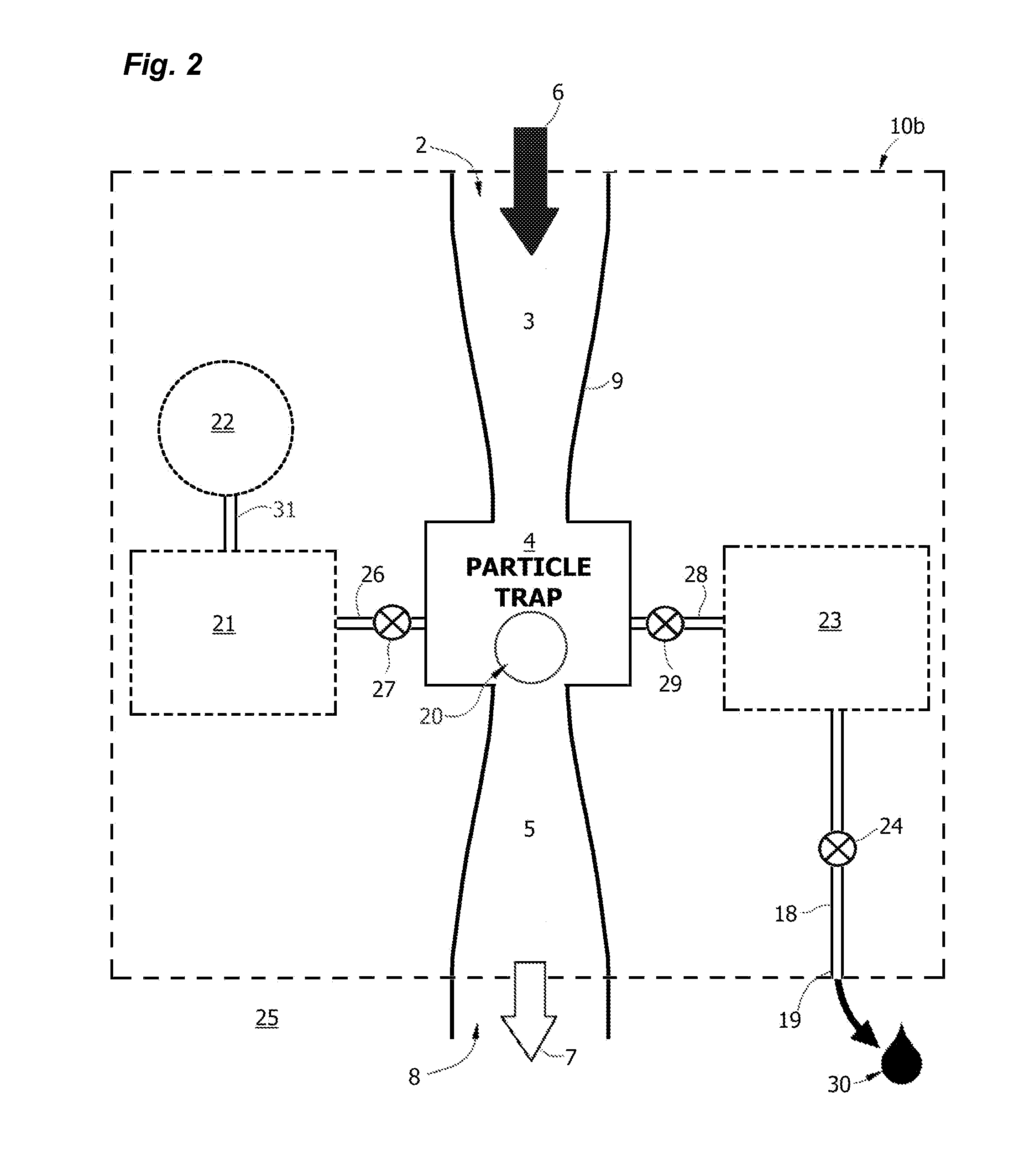
[0018]Using these methods and apparatus, we have discovered that an impacted aerosol particle sample can be eluted from microfluidic-scale impactor surfaces in a constrained space with a very small droplet or a series of droplets of elution fluid, even nanoliter-sized droplets, enabling large concentration factors and increased sensitivity and robustness in detection of aerosol particles or their constituents of interest. The foremost technical advantage is the ability to achieve extremely high concentration factors and prepare the collected sample material for analysis in extremely small droplets in near real time.
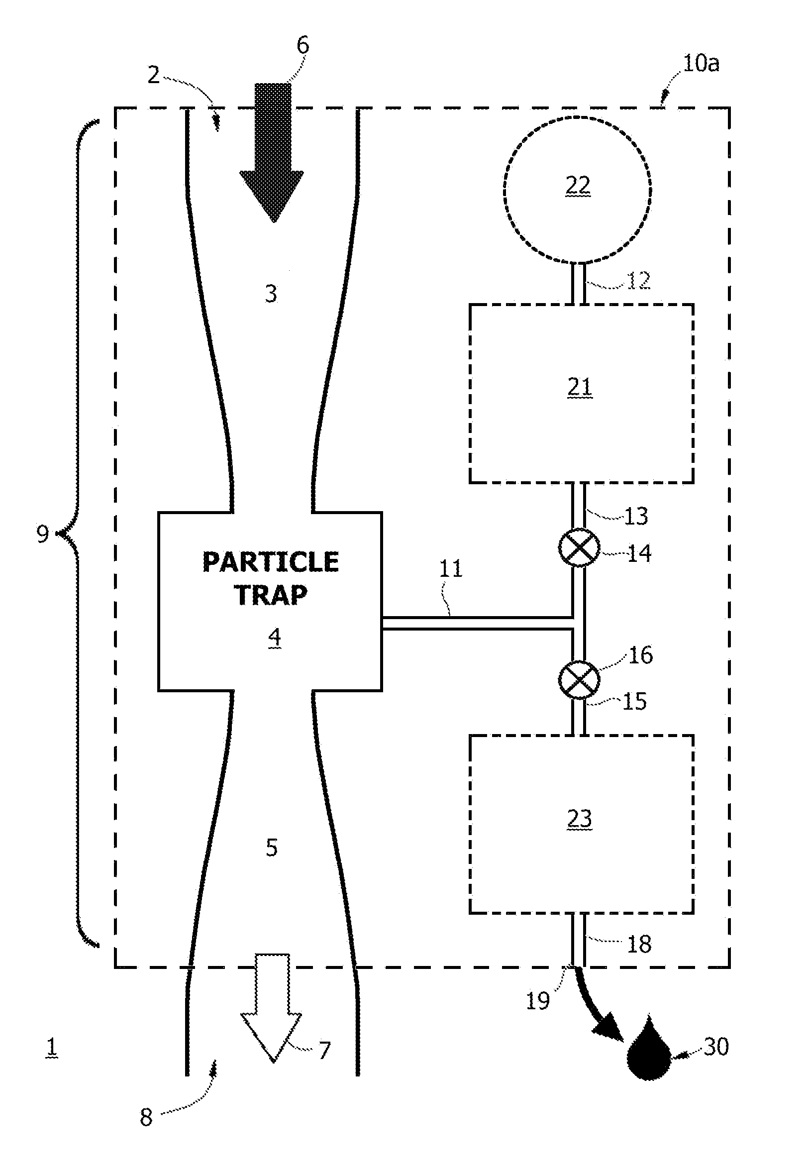
[0025]The invention addresses the problem of collecting aerosol particles from large volumes of air in very small particle traps, and eluting the captive sample material in very small volumes of a liquid reagent, thus achieving extremely high concentration factors relative to the dispersed aerosol and improving sensitivity and robustness of analyses of the captive aerosol particles and their constituents in an air-to-liquid aerosol concentrator and collector.
[0029]Surprisingly, periodic application of acoustic energy may also be used preventatively so that performance is not affected during extended use without interruption of monitoring. The benefits of “on the fly” prophylactic insonation treatments can be achieved with very low power consumption and without down time. Intermittent pulsatile application of acoustic energy can prevent fouling over an extended lifetime of use, for weeks or months, and in fact improves particle collection efficiency by routine intermittent application of dry acoustic treatments.
[0032]In a preferred embodiment, the initial cleaning event is a “dry cleaning” treatment, where the equipment is treated with acoustic energy without wetting; then if performance is not restored or residual particle buildup is not acceptable, a secondary “wet cleaning” treatment may be performed. This combination of steps is used to clean the equipment of any particle load that would interfere with subsequent detection events. In this way, a next particle sample can be collected without the need to replace the particle accretion surface, and without damage to the workings of the apparatus. This apparatus can be cycled through dry cleaning, wet cleaning, and wet sampling modes semi-continuously, or a wet cleaning cycle and sampling cycle can be triggered only in response to a signal. The apparatus is otherwise cleaned on the fly using dry ultrasound without interruption of gas flow, an advance in the art.
[0035]Instead of having to replace or service aerosol monitoring and particle collection equipment that has become blocked or fouled, captive particles that are trapped on and fouling aerosol concentrator or collector surfaces may be periodically mobilized and removed by application of a brief pulse of acoustic energy, essentially eliminating the progressive deterioration of performance resulting from fouling as is commonly seen with equipment of this type—with only a very low increase in power consumption. In more severe cases of fouling, wet acoustic cleaning may also be used by supplying a liquid injection system in combination with an acoustic transducer. The hydraulics of this system can be adapted so that particle:liquid concentrates in smaller liquid volumes are conveniently sampled for downstream analysis. In combination, dry acoustic cleaning can be used to routinely clear and discard particulate material that is not of interest, but when the particulate material merits further analysis, as when the particulate material meets certain preliminary analysis characteristics, the wet cleaning cycle functions synergically as a gas-to-liquid particle concentrator, generating a concentrated sample in a discrete liquid volume for further study.
[0045]In one embodiment, dry cleaning is performed regularly at intervals as experience demonstrates are sufficient to prevent particle build-up. In yet another aspect, the invention incorporates a sensor or sensors and control circuitry to trigger dry and / or wet acoustic cleaning in a feedback loop where operating parameters are continuously sensed and cleaning is performed to maintain or restore optimal efficiency: first by dry acoustic cleaning without interruption of gas flow, then if desired by wet acoustic cleaning to remove more stubborn deposits, or to obtain a liquid sample. Wet sampling may be initiated in response to an accumulation of a particle mass or by detection of a target particle constituent, for example by spectroscopic or fluoroscopic characterization of the particle mass in situ in the particle trap prior to sampling. In this way, unnecessary down time and exhaustion of time or resources on uninteresting or information-poor samples are avoided.

Problems solved by technology

However, unless first eluted from the impactor surface, these adherent sample materials are not generally accessible for many kinds of analyses.
Inability to elute the sample material in a liquid volume can result in failure to detect a bioaerosol, particulate toxin or other aerosol particle of interest.

Method used


Image

  • Aerosol Collection Apparatus and Methods
  • Aerosol Collection Apparatus and Methods
  • Aerosol Collection Apparatus and Methods

Examples


example 1

Dry Acoustic Cleaning of an Aerosol Concentrator

[0350]An aerosol concentrator with ADL and skimmer of the type shown in co-assigned U.S. Pat. No. 7,875,095 was set up with flowing air and instrumented to monitor backpressure. ASHRAE dust was then introduced into the feed and backpressure was monitored. After a suitable interval, backpressure in the major and minor flow channels had substantially increased. The skimmer assembly was then subjected to acoustic energy using a piezoelectric horn contacted to the body of the skimmer. Backpressure immediately returned to pre-fouling levels. As shown in the table below, backpressure in the major flow channels was seen to rise from 5.5 to 12 inches H2O with increased narrowing due to accumulation of ASHRAE dust in the channels. Upon application of ultrasound to the body of the assembly, backpressure immediately returned to baseline. Similarly, in the minor flow channel, backpressure rose from 0.3 to 1.8 inches H2O, but returned to 0.3 inches...

example 2

Prophylaxis

[0351]In a second example, prophylactic treatment was demonstrated. Using the setup of Example 1, ASHRAE dust was again introduced into an aerosol concentrator. A flow split of 40:1 was used; with 10 Lpm flow rate in the chimneys and 0.25 Lpm in the collector channel. Rather than permit fouling to occur, ultrasound (33 KHz, 50 W) was applied for 1 second at 2 minute intervals. Backpressure was again monitored.

[0352]After 30 minutes, no increase in backpressure was noted in any of the channels of the device. Contrastingly, backpressure had noticeably increased under control conditions without ultrasonic prophylaxis of fouling. Visual inspection confirmed that particle deposits were prevented by periodic ultrasonic treatments.

Backpressure, Major FlowBackpressure, Minor FlowExperimentalChannels (inches H20)Channel (inches H20)Intermittent US30Treatment over30 minNegative30.3Control

[0353]The reduced duty cycle (1 sec ON at 2 min intervals) reduced energy consumed in the ultra...

example 3

Timecourse for Fouling Under Heavy Loading

[0355]Using the setup described in the examples above, the data of FIG. 34 was obtained by monitoring backpressure over a thirty minute interval. Backpressure is reported as percent over baseline. Backpressure in the chimney of the untreated channel continued after ten minutes but increases are not shown because the pressure gauge had reached its maximum reading.


PUM


Abstract

The lifetime of aerosol monitoring, concentration and collection equipment is extended by acoustic cleaning of accreted particle deposits from internal surfaces where fouling occurs by application of acoustic energy to the particle accretion surface, optionally in combination with a liquid wash or sampling volume. In one application, acoustic cleaning or sampling of particle deposits for analysis is triggered by a signal indicating changes in gas flow associated with particle loading. In another application, electro-acoustic transducers may be used to prevent particle buildup without interruption of particle monitoring.

Description

RELATED APPLICATIONS[0001]The present application is a Continuation-In-Part of U.S. patent application Ser. No. 12 / 364,672 filed 3 Feb. 2009, which claims the benefit of priority under 35 USC 119(e) Provisional Pat. Appl. No. 61 / 026,376 filed on 5 Feb. 2008, said patent documents being incorporated herein in entirety for all purposes by reference.GOVERNMENT SUPPORT[0002]The United States Government has rights in this invention pursuant to Grant No. NBCHC060109 awarded by the Department of Homeland Security, and Grant No. 1R43ES016390-01 awarded by the National Institutes of Health.BACKGROUND[0003]Aerosols from natural, anthropogenic and industrial sources have long been recognized as a potential threat to human health; to that list of sources we now must add airborne chemical or biological warfare agents as a source of potentially lethal exposure or terrorist threat. Effective sampling and collection of aerosol particles is a critical first step in the detection and identification o...

Claims


Application Information

Patent Timeline
IPC IPC(8): G01N7/00
CPCB08B3/12B08B7/026G01N1/2202G01N1/2208G01N1/2211G01N15/0266G01N2015/0261G01N2001/2223G01N2001/383G01N2015/0038G01N2015/0088G01N2015/0096G01N15/0606B03C3/017B03C3/08B03C3/12B03C3/41B03C3/47B03C2201/04Y10T137/8376G01N2015/019
Inventor ARIESSOHN, PETER C.NOVOSSELOV, IGOR V.DENGLER, EVAN
Owner ENERTECHNIX
Learn More