Infrared light-reflecting film and production method thereof

a technology of infrared light and film, applied in the field of infrared lightreflecting film, can solve the problems of high production cost, low vacuum process productivity, and preventing toll collection system, and achieve the effect of low oxygen concentration and high molecular weigh

Inactive Publication Date: 2012-09-06
FUJIFILM CORP
View PDF5 Cites 12 Cited by
  • Summary
  • Abstract
  • Description
  • Claims
  • Application Information

AI Technical Summary

Benefits of technology

[0063]The production method of the invention includes an irradiation step in which the polymerizable liquid crystal composition is irradiated with actinic radiation to fix the cholesteric liquid crystal phase and form an infrared light-reflecting layer.
[0064]As the actinic radiation, ultraviolet rays or the like can be used. When irradiation with ultraviolet rays is used, a light source such as an ultraviolet ray lamp and the like is used. In this step, by irradiation with ultraviolet rays, the cholesteric liquid crystal phase is fixed, and the infrared light-reflecting layer is formed.
[0065]The energy amount with irradiation of actinic radiation is not particularly limited, but is generally from about 100 mJ/cm2 to 800 mJ/cm2. Further, the time for irradiating the polymerizable liquid crystal composition with actinic radiation is not particularly limited, but is determined from the viewpoints of sufficient strength of a cured film (infrared light-reflecting layer) and productivity.
[0066]In order to promote the reaction for fixing the cholesteric liquid crystal phase, irradiation with actinic radiation under a heating condition may be carried out. Further, it is preferable to maintain the temperature during irradiation with actinic radiation to a temperature range showing the cholesteric liquid crystal phase and not so as to deform the cholesteric liquid crystal phase. In addition, the oxygen concentration under a curing reaction atmosphere is involved in the degree of polymerization. For this reason, a desired degree of polymerization is not attained with a curing reaction in air, and when the film strength is not sufficient, it is

Problems solved by technology

The coating of the special metal film produced by the use of the vacuum film-forming method is excellent in reflection performance, but the vacuum process is low in productivity, whereby the production cost thereof is high.
When a metal film is used, there i

Method used


Image

  • Infrared light-reflecting film and production method thereof
  • Infrared light-reflecting film and production method thereof
  • Infrared light-reflecting film and production method thereof

Examples


example 1

Preparation of Coating Liquid (Polymerizable Liquid Crystal Composition)

[0206]First, a coating liquid having the composition of Example 1 shown in Table 1 below was prepared.

[0207](Coating, and Film Formation)

[0208]The prepared coating liquid was coated onto the surface of a PET film having a thickness of 50 μm, manufactured by FUJIFILM, at room temperature using a wire bar so as to have a thickness of the dried film of about 4 to 5 μm;

[0209]the film was dried at 30° C. for 30 seconds, and then heated in an atmosphere at 100° C. for 2 minutes to form a cholesteric liquid crystal phase; and

[0210]subsequently, controlling the output of the lamp using a metal halide lamp manufactured by Eye Graphics at 30° C., this was irradiated with UV rays in a nitrogen-purged atmosphere at a dose of 28.3 mW / cm2 for 3 seconds to fix the cholesteric liquid crystal phase and to form an infrared light-reflecting film of Example 1. Further, the amount of the residual solvent after the drying step ((the ...

example 15

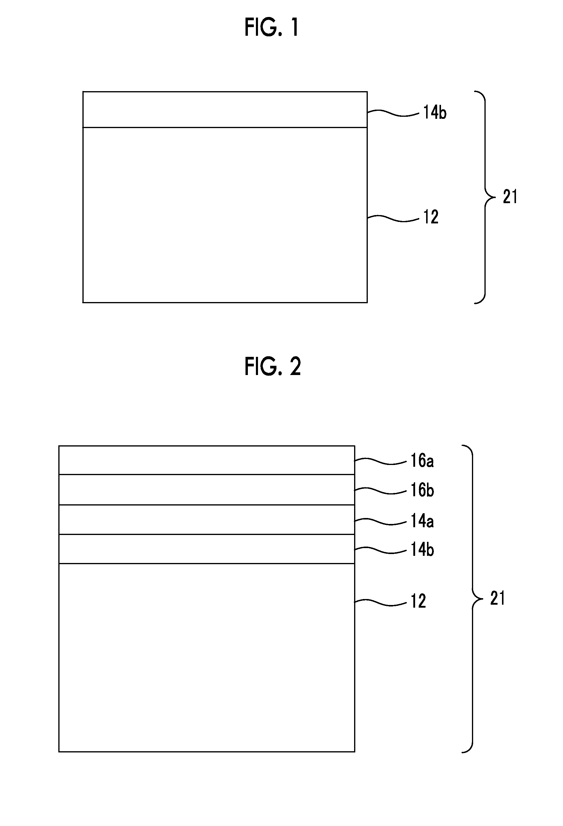
[0227]In the same manner as in Example 1 except that the number of the infrared light-reflecting layers was 3, an infrared light-reflecting film was produced. With respect to the obtained infrared light-reflecting film, the haze was measured by the same method as in Example 1. As a result, even when the number of the infrared light-reflecting layers was 3, an infrared light-reflecting film having the same alignment as in Example 1 was obtained.

example 16

[0228]In the same manner as above except that the infrared light-reflecting layer (also referred to as a first layer) laminated in Example 1 was cooled to room temperature, and then the chiral agent (B-3) for left-handed twisting used in Example 1 was changed to the chiral agent (B-4) for right-handed twisting as described below, a second layer was formed on the first layer of the infrared light-reflecting layers. Further, the peak of the reflection wavelength of the light-reflecting film after formation of the second layer was 1000 nm. In addition, in the same manner as in Example 1 except that the chiral agent (B-3) for left-handed twisting and the chiral agent (B-4) for right-handed twisting were used alternately on the second layer after adjusting to such a concentration that the peak of the reflection wavelength was 1120 nm, the third layer and the fourth layer were laminated. Subsequently, in the same manner, as in Example 1 except that the chiral agent (B-3) for left-handed t...


PUM

PropertyMeasurementUnit
Percent by massaaaaaaaaaa

Abstract

A method of producing an infrared light-reflecting film includes a coating step of coating a polymerizable liquid crystal composition including a polymerizable cholesteric liquid crystal compound (A), a chiral agent having an HTP of 50 μm−1 or less (B), a monofunctional monomer (C), and an organic solvent (D) on a substrate, an alignment step of aligning the polymerizable cholesteric liquid crystal compound by heating to form a cholesteric liquid crystal phase, and an irradiation step of irradiating the polymerizable liquid crystal composition with actinic radiation to fix the cholesteric liquid crystal phase and form an infrared light-reflecting layer, wherein the amount of a residual solvent after the alignment step is controlled to 0.20 g/m2 or more.

Description

BACKGROUND OF THE INVENTION[0001]1. Field of the Invention[0002]The present invention relates to an infrared light-reflecting film that has a layer formed by fixing a cholesteric liquid crystal phase, and a production method thereof.[0003]2. Description of the Related Art[0004]With the recent increase of concern over and interest in the environment or energy, energy-saving industrial products have been increasingly demanded. For example, glass and films have been required which could effectively shield glass windows of houses or vehicles from heat, that is, effectively reduce the thermal load due to solar rays. In order to reduce the thermal load due to solar rays, it is necessary to prevent the transmission of some solar rays in the visible light region or the infrared light region in a solar light spectrum. Particularly, from the viewpoint of safety, high transmittance to the visible light region and heat-shielding performance are actively required for vehicle windows, and the ref...

Claims


Application Information

Patent Timeline
IPC IPC(8): C09K19/00B32B37/02B05D3/06B32B37/14B05D5/06B05D3/02
CPCB32B33/00B32B2037/243B32B2305/55B32B2307/416B32B2310/0837G02B5/3016C09K19/586C09K2019/0448C09K2219/03G02B5/208B32B2367/00
Inventor MAJIMA, WATARUOKI, KAZUHIRO
Owner FUJIFILM CORP
Why Eureka
Try Eureka