
Fluorescent particle, with semiconductor nanoparticles dispersed therein, fabricated by the sol-gel process

Inactive Publication Date: 2012-11-29
NAT INST OF ADVANCED IND SCI & TECH
View PDF0 Cites 8 Cited by
  • Summary
  • Abstract
  • Description
  • Claims
  • Application Information

AI Technical Summary

Benefits of technology

[0046]The fluorescent fine particles of the present invention contain a dispersion of a considerable amount of semiconductor nanoparticles having durability and high PL efficiency, and the surface of thereof is coated with appropriately hydrolyzed alkoxide. These semiconductor nanoparticles form an assembly of an appropriate size, and the circumference of the assembly is coated with silica glass. Therefore, the present invention achieves the effect of providing two characteristics, i.e., high durability and high brightness. Further, because the average particle size is 20 to 100 nm, the fluorescent fine particles are applicable as fluorescent probes in the field of biotechnology. The semiconductor nanoparticle assembly being coated with silica glass can be confirmed by analysis of the coated portion using an analytical electron microscope because the results show that silicon and oxygen are contained. It can also be confirmed from the fact that powder X-ray diffraction (irradiation with copperray, at 1.5406 angstrom) of vacuum-dried powder sample shows a broad diffraction peak (a full width at half-maximum of 5 degrees or more) near an angle (20) of 23 degrees.

Problems solved by technology

However, it has been reported that while the alkylamine ligands improve the PL efficiency by eliminating surface defects, a ligand ((Et-O)3—Si—O−) comprising a partially hydrolyzed alkoxide has a quenching effect, which causes a rapid decrease in the PL efficiency.
Specifically, it became clear that hydrolyzed alkoxide itself does not have a quenching effect, but quenching results from random aggregation of alkoxides on the nanoparticle surface, an insufficient number of alkoxide bound to the surface, and the like.
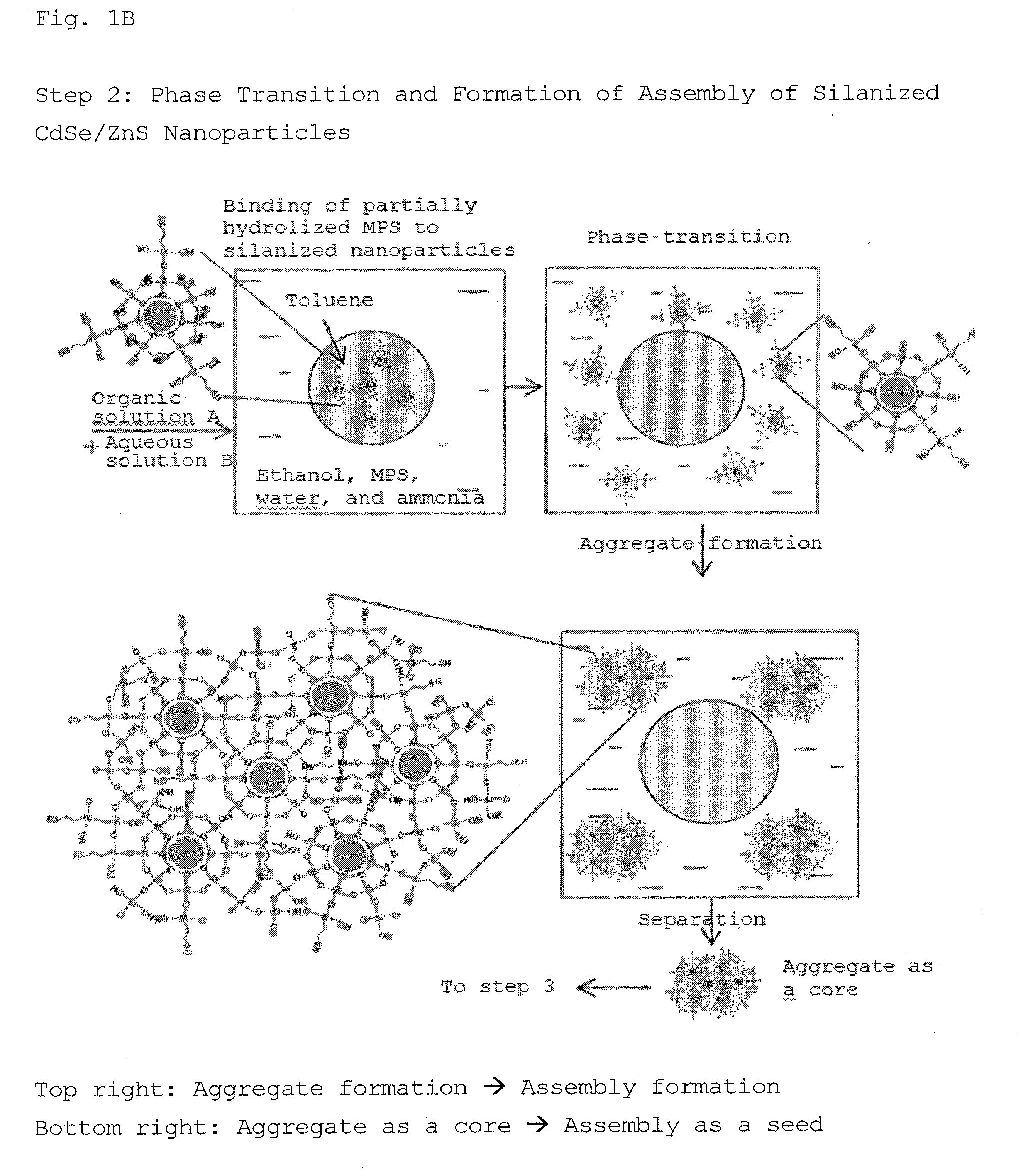
When the stirring time is shorter than the above range, there is a tendency for transfer to the aqueous phase to not be easily carried out in the subsequent third step because the amount of hydrolyzed metal alkoxides (1) bound to the nanoparticle surface is small.
Further, when the stirring time is longer than the above range, there is a tendency for the PL efficiency to decrease and agglomeration to occur because too many hydrolyzed metal alkoxides (1) are bound to the nanoparticle surface.
Herein, if TEOS or the like used as the metal alkoxide (1) is used as the metal alkoxide (2), the size of the assemblies will rapidly increase in the aqueous phase, causing white turbidity.
When the nanoparticles are converted to the aqueous phase, the hydrolysis reaction proceeds rapidly and randomly, resulting in a large assembly and white turbidity of the solution, if no countermeasure is taken.
However, when the dissolved Cd is quantified using the filtrate, the dissolution amount decreases with time.

Method used


Image

  • Fluorescent particle, with semiconductor nanoparticles dispersed therein, fabricated by the sol-gel process
  • Fluorescent particle, with semiconductor nanoparticles dispersed therein, fabricated by the sol-gel process
  • Fluorescent particle, with semiconductor nanoparticles dispersed therein, fabricated by the sol-gel process

Examples


example 1

Synthesis of Silica Glass Fine Particles

[0116]CdSe / ZnS nanoparticles (CdSe core, ZnS shell) whose surface is coated with dodecylamine were prepared by a known method (Nano Letters, Vol. 1, p. 207 (2001) and Colloids and Surfaces A, Vol. 202, p. 145 (2002)). The nanoparticles were dispersed at a concentration of 20 μM in a toluene solution. The PL efficiency was measured to be 35%. The emission wavelength was about 620 nm, and the half-bandwidth (full width at half-maximum) of the emission spectrum was about 33 nm.

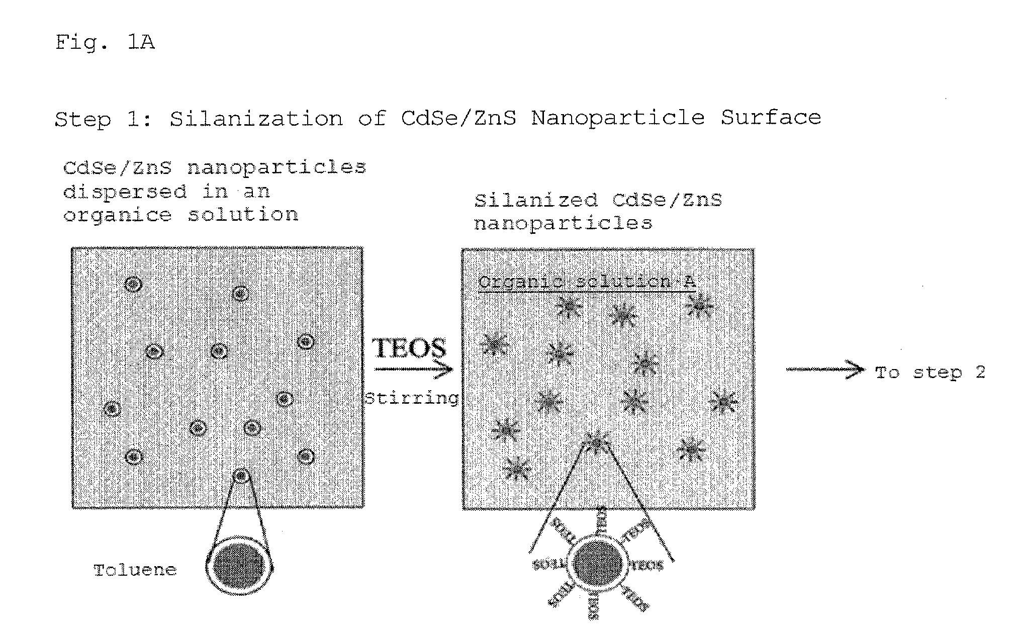
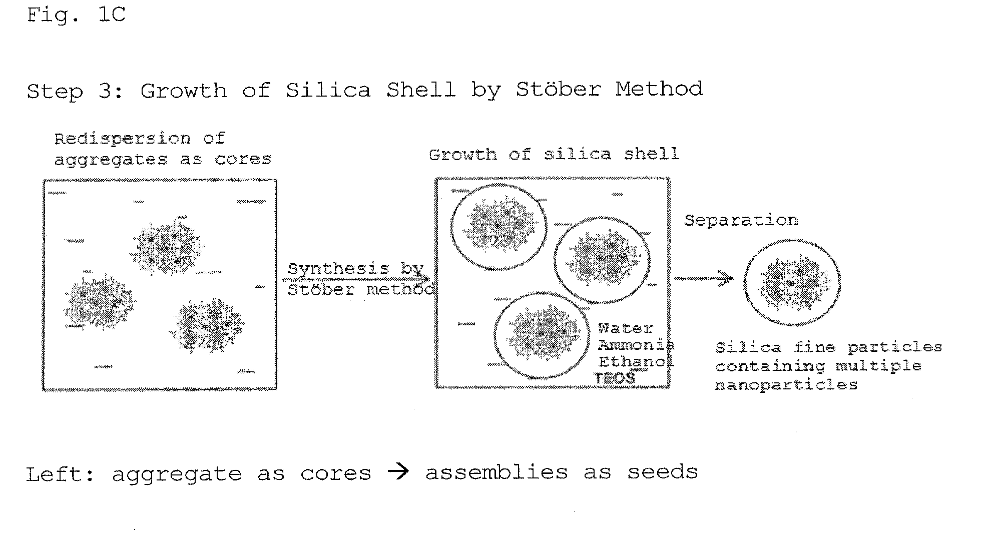
[0117]Next, silica glass fine particles in which fluorescent nanoparticles are dispersed were prepared via 3 stages from step 1 to 3 shown in FIGS. 1A to 1C. Unless otherwise stated, the synthesis was carried out at room temperature in the atmosphere.

[0118]In step 1, tetraethoxysilane (TEOS, 10 μL) was added to a toluene solution in which nanoparticles are dispersed (0.4 mL, 1.5 μmol / L), and the mixture was stirred for 3 hours, thereby obtaining organic solution A. In regar...

example 2

[0133]Hydroxyl groups are present on the surface of the silica glass fine particles prepared in Example 1. In order to apply the silica glass fine particles as fluorescent probes in the field of biotechnology, the surface of the silica glass fine particles were modified with various functional groups; and further, antibodies were conjugated thereto.

[0134]When MPS was used after the formation of a silica glass layer in Example 1, fine particles coated with thiol groups were prepared.

[0135]The fine particles after the formation of the silica glass layer were dispersed in pure water, and 0.5 mL of fine particles (nanoparticle concentration of 1 μM) was extracted and added to a mixture of MPS (2 μL) and ethanol (30 μL). After stirring, precipitate was obtained by centrifugation, washed with pure water, and dispersed in a PBS (concentration: 10 μM) solution to obtain an amount of 0.5 mL. 0.1 mL was extracted therefrom, and a PBS buffer solution (10 μL) in which the concentration of strep...

example 3

[0148]When the amount of MPS used in “Synthesis of Silica Glass Fine Particles” in Example 1 was decreased to 0.5 μL, the size of nanoparticle assemblies formed was increased. The surface of these assemblies was coated with silica glass in the same manner as in Example 1, thereby obtaining fluorescent fine particles. At this time, the PL efficiency when the semiconductor nanoparticles were dispersed at a concentration of 10 nmol / L in a HEPES solution was about 25%. It was found by electron microscope observation that the fluorescent fine particles have an average particle size of 95 nm. Further, it was confirmed that at least 160 nanoparticles are dispersed.


PUM


Abstract

An object of the present invention is to prepare a fine particle with high durability and high brightness, in which semiconductor nanoparticles are assembled. The present invention provides fluorescent fine particles comprising Cd- and Se-containing semiconductor nanoparticles dispersed in silicon-containing fine particles, wherein the average particle size of the silicon-containing fine particles is 20 to 100 nm, and the number of semiconductor nanoparticles dispersed in the silicon-containing fine particles is 10 or more.

Description

TECHNICAL FIELD[0001]The present invention relates to a method for preparing highly durable silica glass fine particles in which numerous semiconductor nanoparticles with high photoluminescence (PL) efficiency are dispersed therein, and an application thereof.BACKGROUND ART[0002]Because fluorescent materials (phosphors) obtained by dispersing rare-earth ions, transition metal ions, and the like in inorganic materials have better durability than organic dyes, these fluorescent materials have been conventionally used for lights, displays, and the like. However, because the brightness and color-rendering properties thereof are not always sufficient, there has been a demand for a fluorescent material with higher brightness. In recent years, semiconductor nanoparticles (particle size of several nanometers; without doping of rare-earth ions or transition metal ions; hereinafter also simply referred to as “nanoparticles” or “quantum dots”) are gaining attention as a high-performance fluore...

Claims


Application Information

Patent Timeline
IPC IPC(8): G01N21/64B82Y15/00
CPCC09K11/565C09K11/883C09K11/025H01L33/0083Y10S977/774Y10S977/779Y10S977/824
Inventor MURASE, NORIOYANG, PINGANDO, MASANORI
Owner NAT INST OF ADVANCED IND SCI & TECH
Learn More