
Membrane Detector for Time-of-Flight Mass Spectrometry

a time-of-flight and mass spectrometry technology, applied in the field of membrane detector for time-of-flight mass spectrometry, can solve the problems of low overall efficiency, low overall efficiency, and large sample size of conventional mass spectrometry analysis of biomolecules, and achieve the reduction or minimal deadtime between measurements, increase the recovery time of the detector and detection method, and reduce the voltage threshold

Active Publication Date: 2012-12-06
WISCONSIN ALUMNI RES FOUND
View PDF6 Cites 31 Cited by
  • Summary
  • Abstract
  • Description
  • Claims
  • Application Information

AI Technical Summary

Benefits of technology

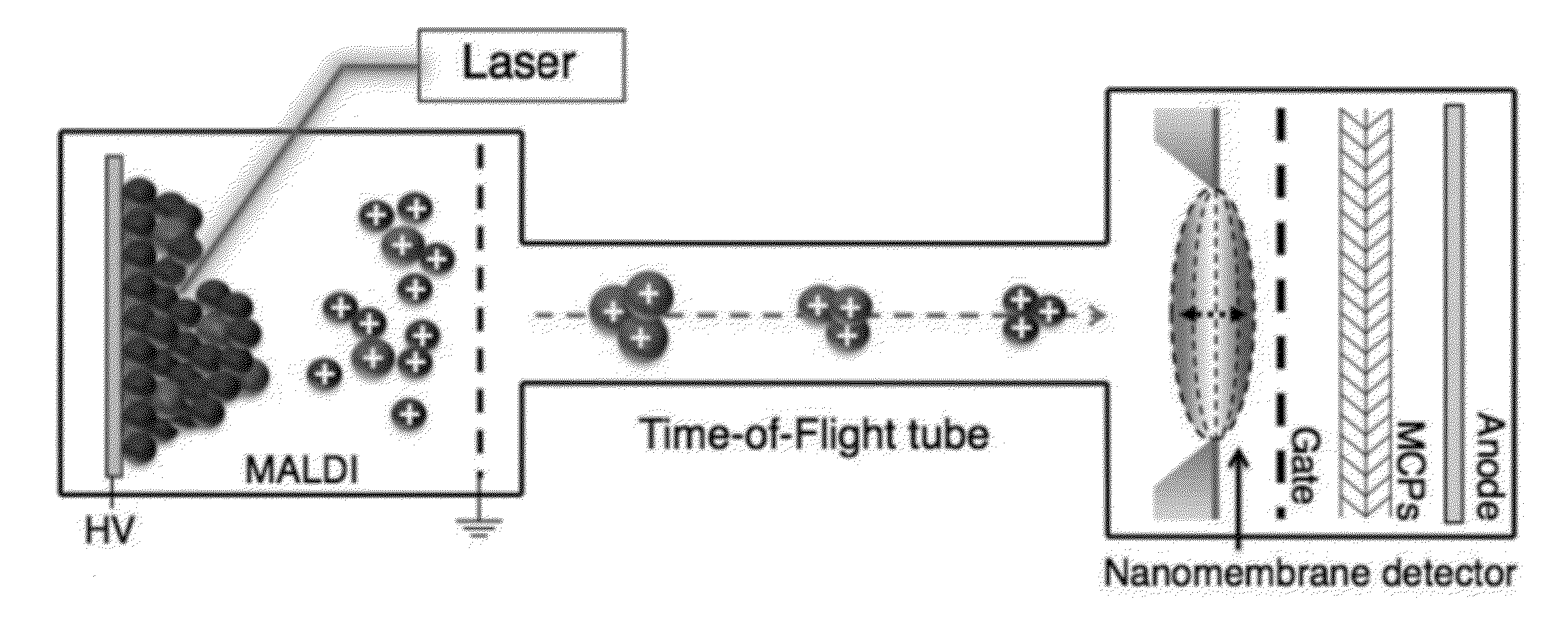
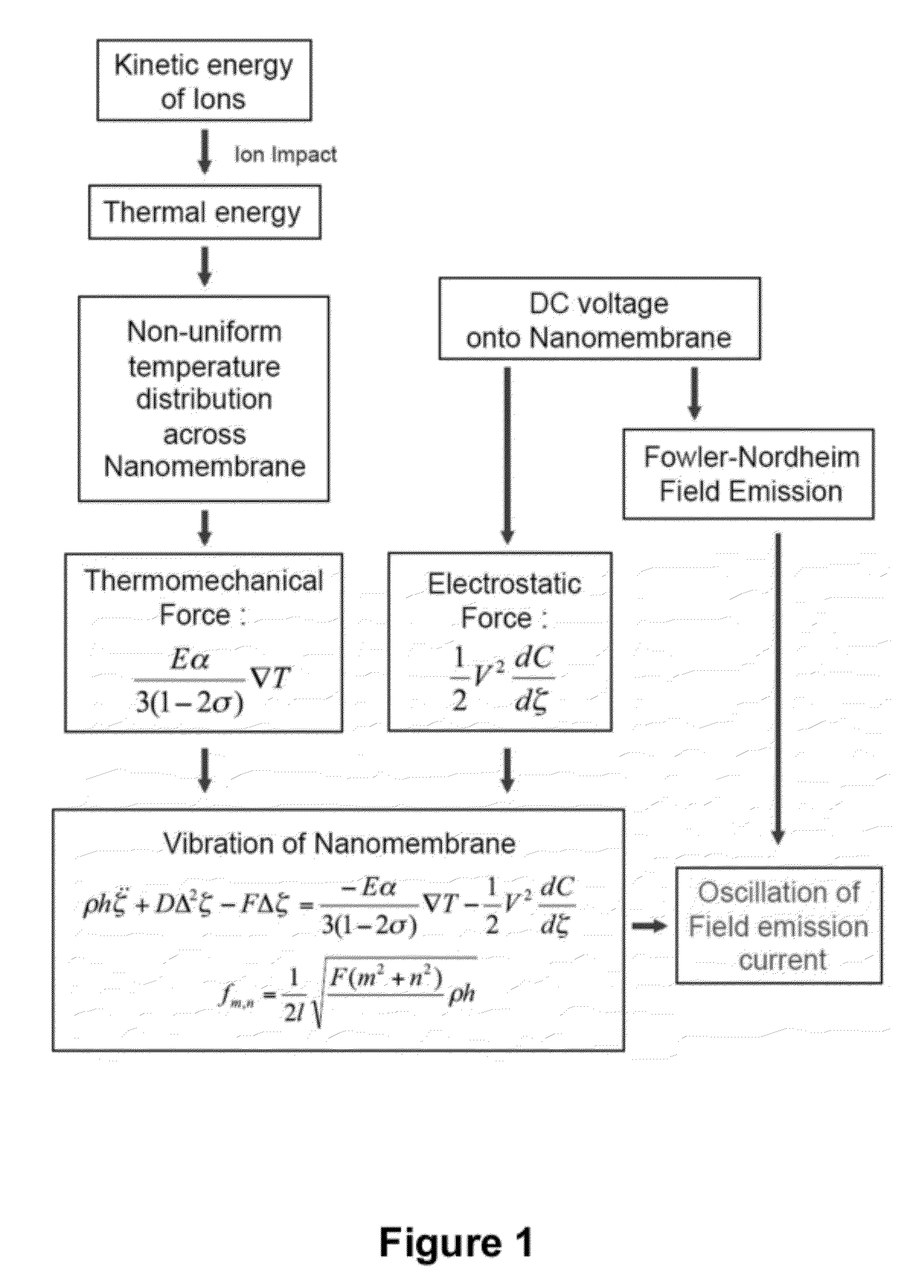
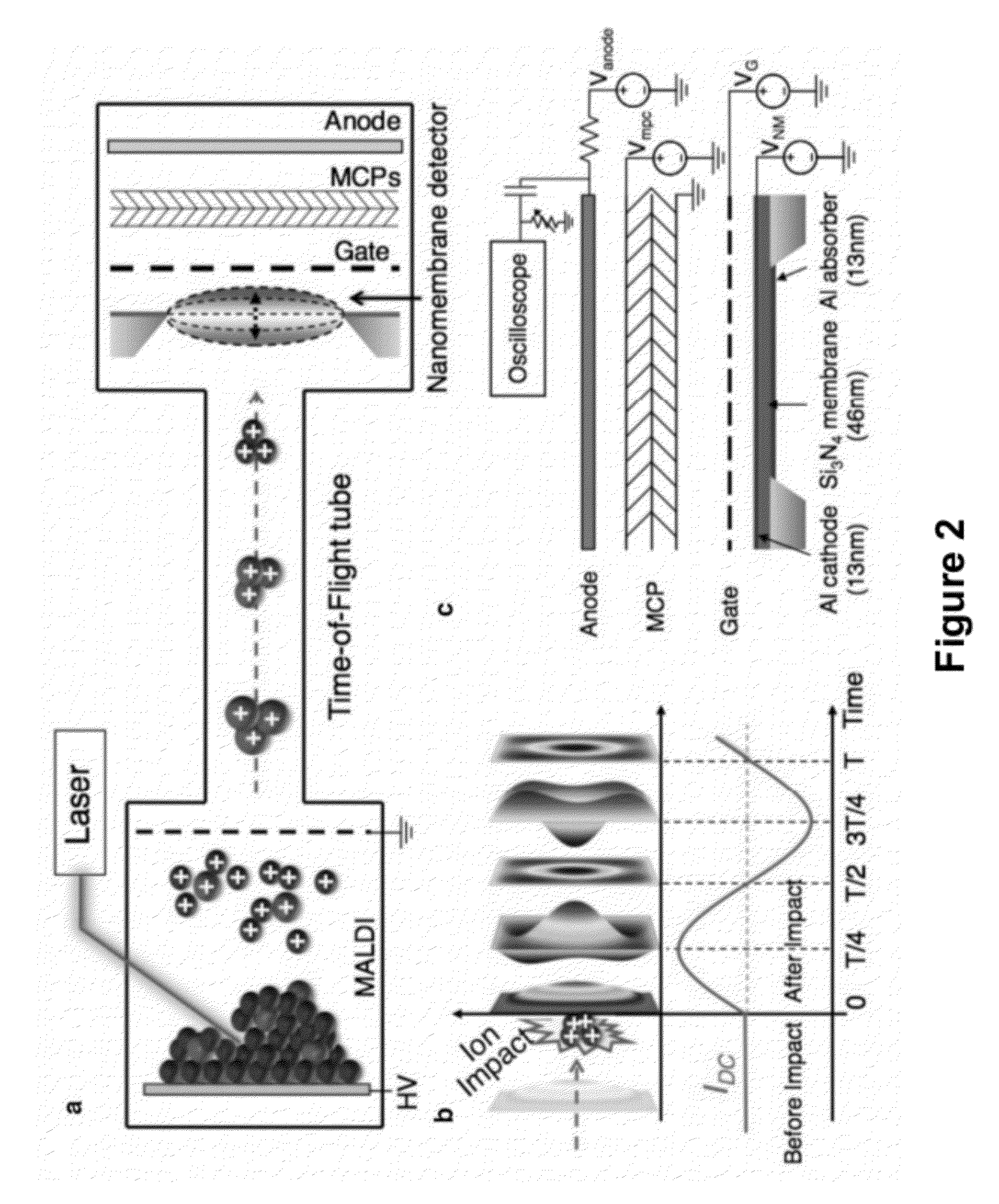
The invention provides methods, devices, and systems for detecting, sensing, and analyzing analytes in biological samples. The methods use a thin membrane detector that can detect analytes with high sensitivity and good temporal resolution. The detector can be used in combination with various ionization systems and mass analyzers for mass spectrometry applications. The method involves generating a non-uniform temperature distribution on the membrane by contact with the analytes, which modulates the field emission of electrons from the membrane. The emitted electrons are then detected and analyzed to provide information about the analytes. The invention has been found to be useful in biomolecule analysis and can be used in proteomics and micro-array analysis.

Problems solved by technology

Despite wide adoption of mass spectrometry for identifying and characterizing biomolecules, conventional state of the art mass spectrometers have surprisingly low overall efficiencies for these compounds.
As a result of low overall efficiency, conventional mass spectrometric analysis of biomolecules typically requires large samples and is unable to achieve the ultra-low sensitivity needed for many important biological applications, such as single cell analysis of protein expression and post-translational modification.
Although integration of modern ionization techniques and time-of-flight analysis methods has expanded the mass range accessible by mass spectrometric methods, complementary ion detection methods suitable for time of flight analysis of high molecular weight compounds, including many biological molecules, remain considerably less well developed.
Indeed, effective upper limits of mass ranges accessible by state of the art MALDI-TOF and ESI-TOF analysis techniques are limited by the sensitivity of conventional ion detectors for high molecular weight ions.
A number of limitations of MCP detection systems arise out of the impact-induced mechanism governing the generation of secondary electrons.
First, the yield of secondary electrons in a MCP detector decreases significantly as the velocities of ions colliding with the surface decreases.
Third, it is also established that once a cascade has been initiated within a channel, it is depleted of electrons.
As apparent to those skilled in the art of mass spectrometry, these limitations impact the utility of MCP detectors for certain mass spectrometry applications by hindering quantitative analysis of samples containing high molecular weight biopolymers.

Method used


Image

  • Membrane Detector for Time-of-Flight Mass Spectrometry
  • Membrane Detector for Time-of-Flight Mass Spectrometry
  • Membrane Detector for Time-of-Flight Mass Spectrometry

Examples


example 1

A Mechanical Nanomembrane Detector for Time-of-Flight Mass Spectrometry

Abstract

[0089]A mass spectrometer is a system comprised of three major parts: an ionization source, which converts molecules to ions; a mass analyzer, which separates ions by their mass to charge ratio; and an ion detector. Mass spectrometry was revolutionized in the late 1980s by the invention of electrospray ionization (ESI)1 and matrix-assisted laser desorption / ionization (MALDI)2,3, which jointly provided means of generating ions from previously inaccessible large molecules such as proteins and peptides. Mass analyzer designs have since evolved to accommodate the large ions that are produced, providing dramatic improvements in performance. However, little has changed in the area of ion detection, where ions continue to be detected by one of three basic principles4: direct charge detection (as in the Faraday cup detector), image charge detection (as in the inductive detector), or secondary electron generation ...

example 2

Quasi-Dynamic Mode of Nanomembranes for Time-of-Flight Mass Spectrometry of Proteins

[0174]Mechanical resonators realized on the nano-scale by now offer applications in mass-sensing of biomolecules with extraordinary sensitivity. The general idea is that perfect mechanical biosensors should be of extremely small size to achieve zepto-gram sensitivity in weighing single molecules similar to a balance. However, the small scale and long response time of weighing biomolecules with a cantilever restricts their usefulness as a high-throughput method. Commercial mass spectrometry (MS), such as electro-spray ionization (ESI)-MS and matrix-assisted laser desorption / ionization (MALDI)-time of flight (TOF)-MS are the gold standards to which nanomechanical resonators have to live up. These two methods rely on the ionization and acceleration of biomolecules and the following ion detection after a mass selection step, such as time-of-flight (TOF). Hence, the spectrum is typically represented in m / ...


PUM


Abstract

The invention provides methods, and related devices and device components, for detecting, sensing and analyzing analytes in samples. In some aspects, the invention provides methods, and related devices and device components, useful in combination with a mass analyzer for the mass spectrometric analysis of analytes derived from biomolecules in biological samples including biological fluids cell extracts, and cell lysates. Methods of some aspects of the invention utilize a thin membrane-based detector as a transducer for converting the kinetic energies of analytes into a field emission signal via excitation of mechanical vibrations in an electromechanically biased membrane by generation of a thermal gradient.

Description

CROSS-REFERENCE TO RELATED APPLICATIONS[0001]This application claims the benefit of priority under 35 U.S.C. 119(e) to U.S. Provisional Patent Application 61 / 492,445 filed Jun. 2, 2011, which is hereby incorporated by reference in its entirety to the extent not inconsistent with the disclosure herein.STATEMENT REGARDING FEDERALLY SPONSORED RESEARCH OR DEVELOPMENT[0002]This invention was made with government support under FA9550-08-1-0337 awarded by the USAF / AFOSR. The government has certain rights in the invention.BACKGROUND OF INVENTION[0003]Over the last several decades, mass spectrometry has emerged as one of the most broadly applicable analytical tools for the detection and characterization of a wide class of molecules. Mass spectrometric analysis is applicable to almost any chemical species capable of forming an ion in the gas phase, and, therefore, provides perhaps the most universally applicable method of quantitative analysis. In addition, mass spectrometry is a highly selec...

Claims


Application Information

Patent Timeline
Patent Type & Authority Applications(United States)
IPC IPC(8): H01J49/26
CPCH01J43/246H01J49/26H01J49/025
Inventor BLICK, ROBERTPARK, JONGHOO
Owner WISCONSIN ALUMNI RES FOUND
Learn More