
Impression gingival cuff for dental implants

Active Publication Date: 2013-04-25
FUDIM ZVI
View PDF3 Cites 36 Cited by
  • Summary
  • Abstract
  • Description
  • Claims
  • Application Information

AI Technical Summary

Benefits of technology

The present invention aims to simplify the process of taking impressions for cement-retained restorations using the same method as for natural teeth. Additionally, it allows for the fabrication of a single material analog mould of the patient's mouth, eliminating issues associated with volume instability due to different expansion and shrinkage rates of materials used in conventional implant moulds.

Problems solved by technology

However, this pickup impression technique requires use of additional parts such as: implant analog, impression copings, and impression transfers which have an impact on accuracy and cost of the restoration.
With cement-retained prostheses that use customized abutments, the pickup impression technique cannot be used owing to the unique contour of the abutments.
Another important aspect of different impression techniques is the inaccuracy that they all present.
Perfect passive fit in the interface between an abutment and an implant is difficult to obtain due to the different factors that affect the process of prostheses fabrication, such as different system tolerance, type of abutment, properties of metallic alloy, impression materials, investing, and casting problems.
Moreover, abutment position distortion has often accompanied transfer impression techniques.
Artifacts caused by retraction cord fibres that remain in the sulcus may affect the accuracy of optical impressions.
However, the powders used when making optical impressions to reduce reflectivity and make tooth surfaces measurable can influence impression accuracy by increasing tooth surface thickness.
Significant errors can result from thin impression margins with a radius less than the contacting probe tip.
Unlike direct impression techniques, the indirect scanable body does not retrieve any information about the abutment what may be in some cases indispensable mostly for the aesthetics.
The implant surrounding fibre structure, however, does not provide the same level of support and is not able to prevent the collapse of retracted tissues to the same extent, which complicates attempts to successfully make impressions.
Yet at the same time, clinicians need to ensure that the retraction forces are gentle since patients' perimplant junctional epithelium is more fragile.
Collapse is the tendency of the gum to flatten under forces associated with the use of closely adapted customized impression trays.
Techniques that clinicians have refined to work well for teeth may not address the challenges faced by clinicians in implant dentistry.
Cord: Clinicians place retraction cords by using cord-packing instruments; however, many commonly used hand instruments (such as the Hollenbach carver tip) were not designed for this application.
The forces generated by pointed or wedge-shaped instrument tips may be traumatic to the relatively fragile junctional epithelium around implants, whereas tooth's gingival tissues may be more forgiving of this type of force.
There is no literature describing the use of cord-packing instruments, and the forces involved with cord placement remain undetermined.
The use of a single retraction cord often provides inadequate gingival retraction.
Placement of retraction cords can cause injury to the sulcular epithelium and underlying connective tissues, as shown by the results of experiments involving dogs' teeth.
The filaments or fibres of conventional cords also may cause residual contamination of sulcular wounds, creating foreign body reactions and exacerbating inflammation.
Use of minimal force is necessary when packing cords to protect Sharpey fibres, and application of excessive force is inappropriate because it may cause bleeding, gingival inflammation and shrinkage of marginal tissues.
It is, however, associated with significant local and systemic side effects, which investigators have reported occurring during 33 percent of applications.
Both are haemostatic and retractile, which causes minimal postoperative inflammation at therapeutic concentrations, although concentrated aluminum potassium sulphate solutions can cause severe inflammation and tissue necrosis.
Aluminum chloride is the least irritating of the medicaments used for impregnating retraction cords, but it disturbs the setting of polyvinylsiloxane impression materials.
The two main drawbacks of using chemicals with retraction cords are: a) the occurrence of rebound hyperaemia that often occurs after cord removal, which affects how effectively clinicians can make impressions, and b) inflammatory reactions induced by these chemicals, which can affect the sub epithelial connective tissue.
When clinicians consider all of these factors, they may question whether retraction cords are appropriate for use around implants, given the vulnerability of the junctional epithelium.
As with any foreign materials introduced into the oral cavity, there remains a small risk of residues' persisting in the gingival crevice.
The viscosity of the injectable matrix may not be enough to provide sufficient retraction for deeper subgingival reparations, and aluminum chloride can inhibit the set of polyether and polyvinylsiloxane materials if clinicians do not rinse it away properly before making impressions.
In patients who have deeply placed implants with subgingival margins, however, its value may be somewhat limited by the extent to which such matrices are able to retract effectively.
Potential drawbacks are that it may not improve the speed or quality of retraction obtained and that it likely is less effective with subgingival margins.
The use of Nd:YAG lasers is contraindicated near implant surfaces, because they tend to absorb energy, which causes them to heat up and transmit the heat to bone, owing to the effects of this laser's wavelength on metal.
There is also a tendency for Nd:YAG lasers to damage the fragile sub junctional epithelium at the sulcus base around implants.
The haemostasis achieved with the Er:YAG laser, however, is not as effective as that achieved with the carbon dioxide (CO2) laser.
Therefore, their use may not be practical around deeply placed implant fixtures where a large defect could result.
In addition, in anterior applications in which aesthetics is critical, it may not be desirable to create a trough around the margins, as it may have a detrimental effect on patients' appearances.
Although CO2 lasers may be significantly useful in some implant impression situations, they are invasive, thus failing to meet the ideal objective of a truly conservative technique.
However, Electrosurgery is not recommended around implants because there is significant risk that the contacting electrode may arc by conducting electric current though the metal implant structure to the bone rather than via the more dispersive gingival tissue pathway.
The concentrated electrical current at the tip of electrodes can generate heat, which may cause osseous or mucosal necrosis.
However, rotary curettage is inappropriate for use around implant restorations because of poor tactile control when cutting soft tissue, which could lead to bur contact damage to the implant surface and over instrumentation.

Method used


Image

  • Impression gingival cuff for dental implants
  • Impression gingival cuff for dental implants
  • Impression gingival cuff for dental implants

Examples


Embodiment Construction

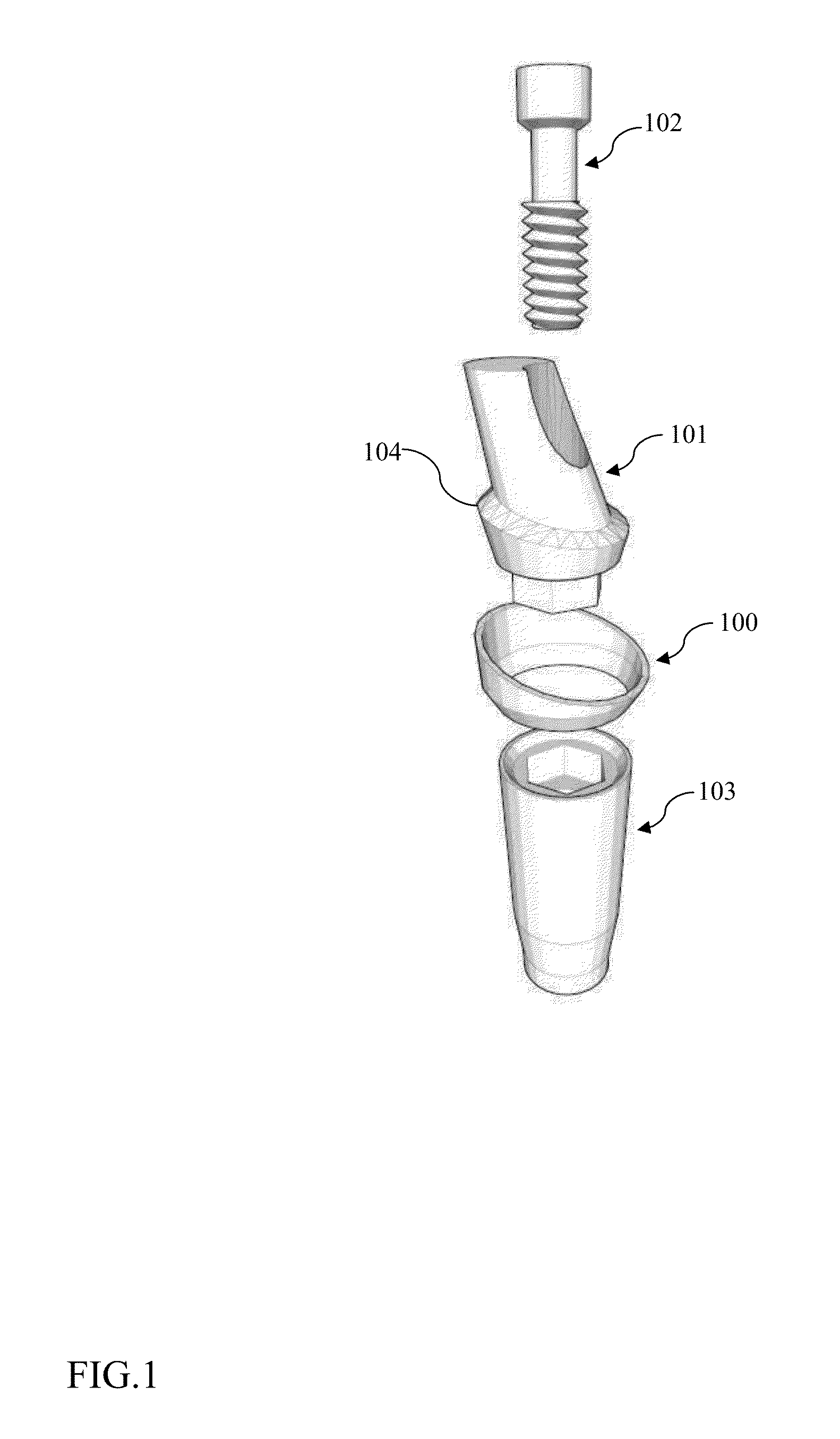
[0108]FIG. 1 demonstrates the sequence of the assembly of a hexed-screw implant 103 and prosthetic accessories such as: an impression gingival cuff 100, an abutment 101, and a connecting screw 102.

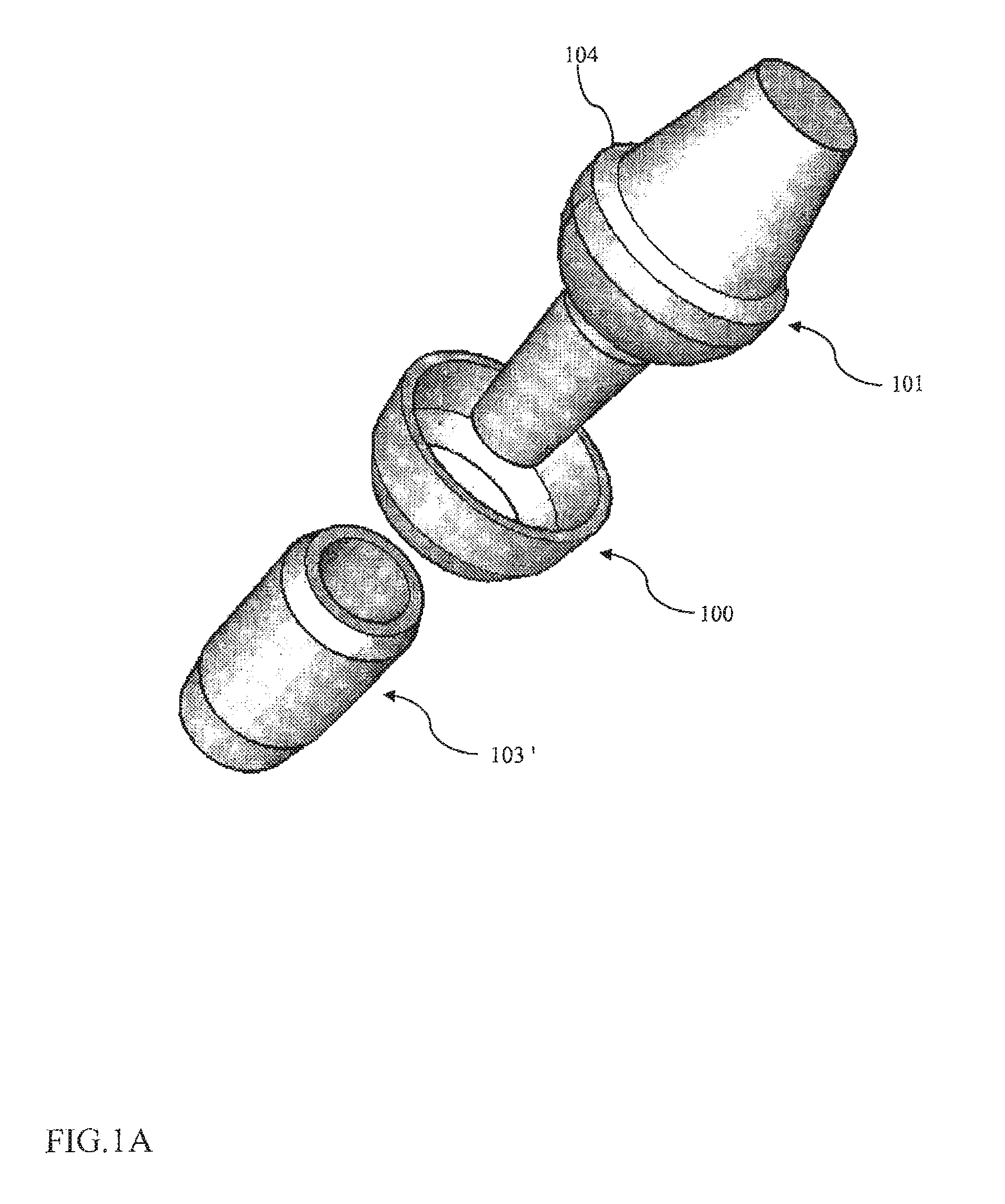
[0109]FIG. 1A demonstrates the sequence of the assembly of cone Morse implant 103 and prosthetic accessories such as: an impression gingival cuff 100, an abutment 101.

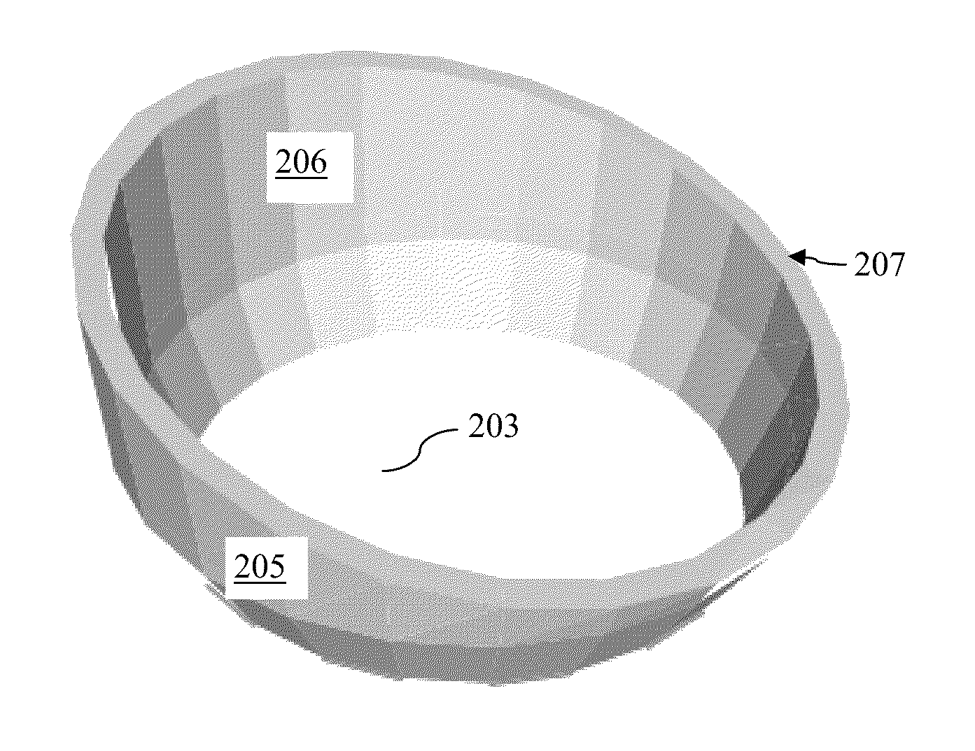
[0110]The Impression Gingival Cuff as shown in FIG. 2 comprising an apical end 204 with apical opening 203 and an occlusal end 202 with occlusal opening 201. The main role of the apical end 204 comprises retention due to the prominent contour 104 of the abutment as it shown in FIG. 1. The outer surface 205 characterized by its convex form divergent towards occlusal. The inner surface 206 characterized by its concave form convergent towards apical.

[0111]The Impression Gingival Cuff as shown in FIG. 2A differs from the one in FIG. 2 by the asymmetry of its wall 207. The asymmetrical wall 207 follows the thickness of the surroun...


PUM


Abstract

An impression gingival cuff for taking an impression during a restoration procedure of a dental implant osteointegrated in a jaw bone. The dental implant is engageably connectable with an abutment having a prominent countour. The impression gingival cuff has a tubular-conical shape, a circumferential thin wall, two open ends including an apical end oriented towards a tooth root and a proximal end oriented towards an occlusal direction, an inner surface oriented towards the abutment and an outer surface oriented towards surrounding gingival tissue. During installation of the cuff between the dental implant and the abutment, the apical end retains the prominent contour of the abutment so that the outer surface of the cuff pushes the surrounding gingival tissue away from the abutment. This allows taking an accurate impression of both the dental implant and abutment in order to fabricate a high precision restoration.

Description

CROSS-REFERENCE TO RELATED APPLICATIONS[0001]This application claims benefit of provisional application No. 61 / 406,159 filed on Oct. 24, 2010.BACKGROUND OF THE INVENTION[0002]1. Field of the Invention[0003]The present invention relates generally to dental implants and, more particularly, methods and devices for impression to restore dental implants. It comes to solve: mould inaccuracies, cost, labour time and infection control problems.[0004]2. Description of Prior Art[0005]“Several impression techniques are used in implant dentistry while some require gingival displacement while making impressions. Others, such as the pickup impression technique, do not require any gingival retraction. However, this pickup impression technique requires use of additional parts such as: implant analog, impression copings, and impression transfers which have an impact on accuracy and cost of the restoration.[0006]For all screw retained implant restorations, most systems use mechanical components (impr...

Claims


Application Information

Patent Timeline
IPC IPC(8): A61C9/00
CPCA61C8/0001A61C8/006A61C9/0033A61C8/0071A61C8/0068
Inventor FUDIM, ZVI
Owner FUDIM ZVI
Learn More