Method and system for electrochemical removal of nitrate and ammonia

a technology of nitrate and ammonia, applied in the direction of electrical-based machining apparatus, water contaminants, water/sludge/sewage treatment, etc., can solve the problems of slow kinetics and generation of byproducts, adverse effects on human health and aquatic ecosystems, and low efficiency of paired electrolysis, so as to achieve high electroactivity and high corrosion resistance. , the effect of high corrosion resistan

Inactive Publication Date: 2013-07-04
TRANSFERT PLUS S E C +1
View PDF5 Cites 15 Cited by
  • Summary
  • Abstract
  • Description
  • Claims
  • Application Information

AI Technical Summary

Benefits of technology

[0006]More specifically, there is provided an electrochemical system for removing nitrate and ammonia in effluents, comprising an undivided flow-through electrolyzer, said electrolyzer comprising at least one cell, each cell comprising at least one anode and one cathode, the cathode being in a copper / nickel based alloy of a high corrosion resistance and a high electroactivity for nitrate reduction to ammonia and the anode being a DSA electrode of a high corrosion resistance and a high electroactivity for ammonia oxidation to nitrogen in presence of chloride.
[0007]There is further provided a method for removing nitrate and ammonia in effluents, comprising providing an undivided flow-through electrolyzer comprising at least one cell comprising at least one anode and one cathode, the cathode being in a copper / nickel based alloy of a high corrosion resistance and a high electroactivity for nitrate reduction to ammonia, and the anode being a DSA electrode of a high corrosion resistance and a high electroactivity for ammonia oxidation to nitrogen in presence of chloride, and circulating the effluents through the electrolyzer.
[0008]There is further provided a method for converting nitrate to nitrogen in an effluent with a N2 selectivity of 100%, a residual nitrate concentration lower than about 50 ppm and an energy consumption as low as 10 kWh / kg NO3−, comprising providing an undivided flow-through electrolyzer comprising at least one cell comprising at least one anode and at least one cathode, the cathode being in a copper / nickel based alloy of a high corrosion resistance and a high electroactivity for nitrate reduction to ammonia, and the anode being a DSA electrode of a high corrosion resistance and a high electroactivity for ammonia oxidation to nitrogen in presence of chloride; maintaining the pH of the effluent above about 9; maintaining a concentration of chloride ions above about 0.25 g / l; and modulating the current between about 1 and 20 mA / cm2 during electrolysis.
[0009]There is further provided a method for converting concentrates of more than 3000 ppm of ammonia in an effluent to nitrogen with an energy consumption around 15 kWh / kg NH3, comprising providing an undivided flow-through electrolyzer comprising at least one cell comprising at least one anode and at least one cathode, the cathode being in a copper / nickel based alloy of a high corrosion resistance and a high electroactivity for nitrate reduction to ammonia, and the anode being a DSA electrode of a high corrosion resistance and a high electroactivity for ammonia oxidation to nitrogen in presence of chloride; maintaining the pH of the effluent above about 9; maintaining a concentration of chloride ions above about 0.25 g / l and modulating the current between about 1 and 20 mA / cm2 during electrolysis.

Problems solved by technology

This pollution has detrimental effects on human health and on the aquatic ecosystems.
Unfortunately, these processes show some drawbacks, such as, for example, the need for continuous monitoring, slow kinetics and generation of byproducts.
In that case, nitrite ions are subsequently oxidized to nitrate at the anode, which strongly decreases the efficiency of the paired electrolysis (Reyter et al., 2010).
This requirement increases the cost and the complexity of the process.
Moreover, during wastewater treatment, the pores of the membrane may be blocked with organic compounds, making it ineffective.
Another limitation of copper is its poor corrosion resistance in presence of chloride, nitrate and ammonia (Korba and Olson, 1992).

Method used


Image

  • Method and system for electrochemical removal of nitrate and ammonia
  • Method and system for electrochemical removal of nitrate and ammonia
  • Method and system for electrochemical removal of nitrate and ammonia

Examples


Embodiment Construction

[0021]The present invention is illustrated in further details by the following non-limiting examples.

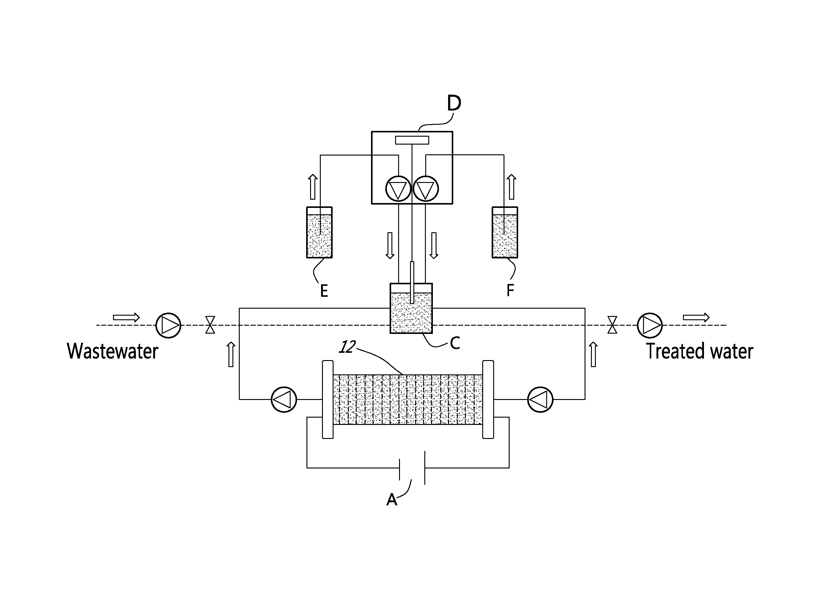
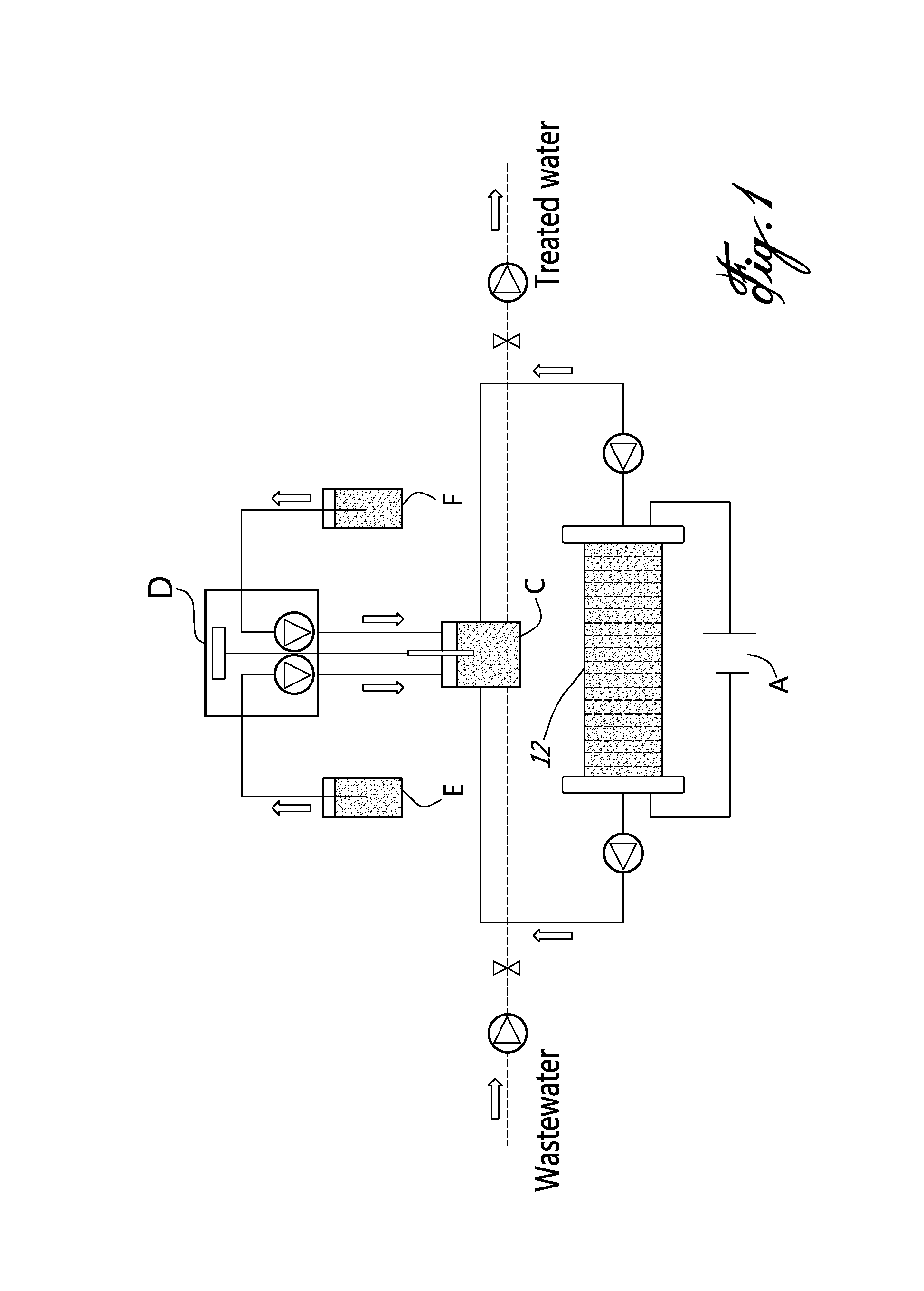
[0022]In a nutshell, there is provided a method and a system for accomplishing conversion of both nitrate and ammonia into nitrogen in a membrane-less multi-electrode electrolyzer comprising electrodes having a high corrosion resistance combined with excellent electroactivities for nitrate reduction to ammonia, at the cathode side, and ammonia oxidation to nitrogen in presence of chlorine, at the anode side.

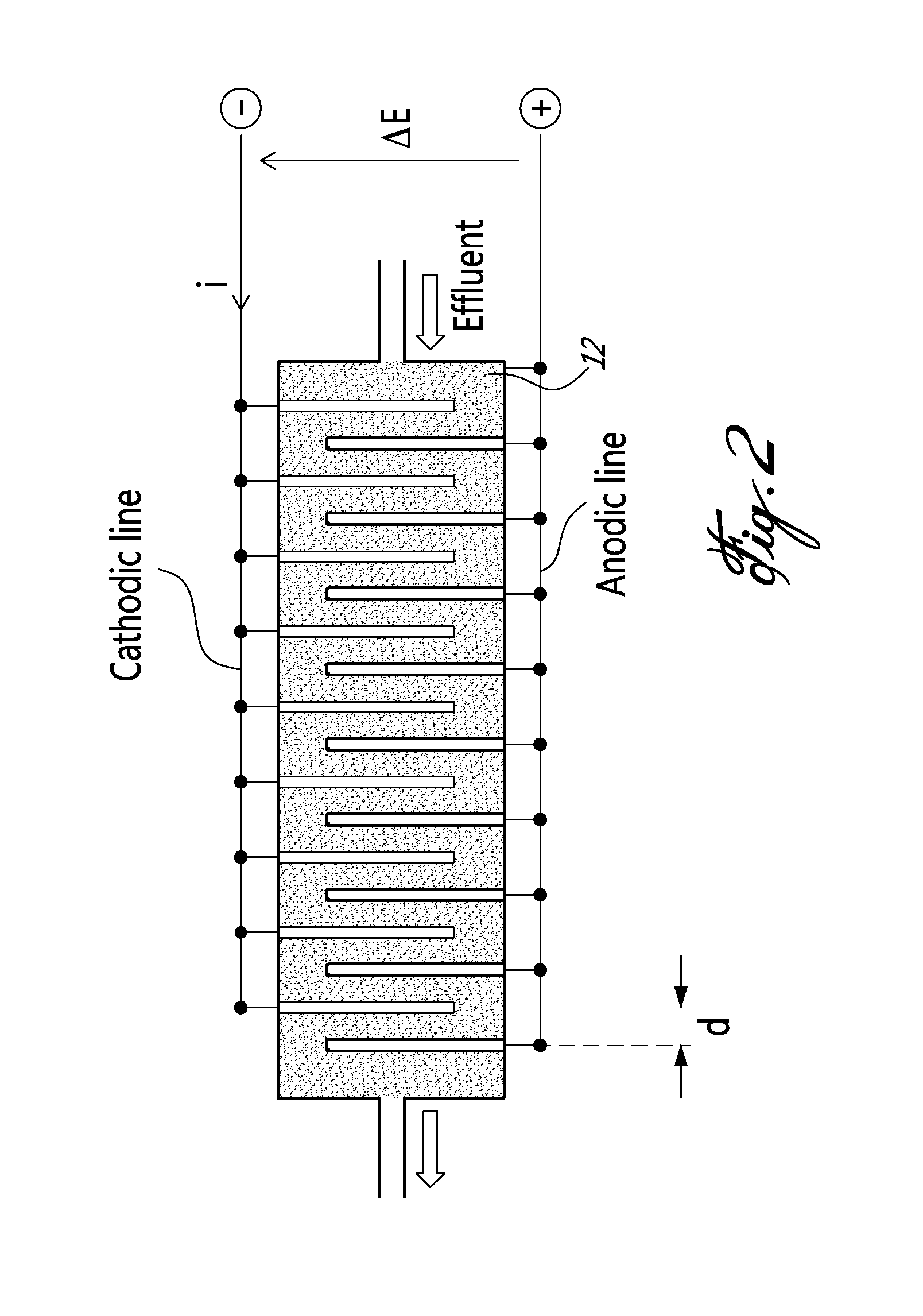
[0023]According to an embodiment of an aspect of the present invention, the system comprises an undivided flow-through electrolyzer. The electrolyzer is thus devoid of membrane, and operates in a single step, which may be advantageous in connection with the removal of nitrate and ammonia over a wide concentration range (from mg / L to g / L) with a low energy consumption.

[0024]The electrolyzer comprises electrodes that are highly resistant to corrosion and highly selective for reducin...


PUM

PropertyMeasurementUnit
concentrationaaaaaaaaaa
current densityaaaaaaaaaa

Abstract

An electrochemical method and system for removing nitrate and ammonia in effluents, using an undivided flow-through electrolyzer, said electrolyzer comprising at least one cell, each cell comprising at least one anode and one cathode, the cathode being in a copper/nickel based alloy of a high corrosion resistance and a high electroactivity for nitrate reduction to ammonia and the anode being a DSA electrode of a high corrosion resistance and a high electroactivity for ammonia oxidation to nitrogen in presence of chloride.

Description

FIELD OF THE INVENTION[0001]The present invention relates to nitrate and ammonia removal. More specifically, the present invention is concerned with a method and a system for electrochemical conversion of nitrate and ammonia to nitrogen.BACKGROUND OF THE INVENTION[0002]Due to the increasing use of synthetic nitrogen fertilizers, livestock manure in intensive agriculture, industrial and municipal effluent discharge, nitrate (NO3−) and ammonia (NH3 / NH4+) contamination in ground and surface waters is now widespread (Puckett, 1995). This pollution has detrimental effects on human health and on the aquatic ecosystems. The World Health Organization recommends a maximum limit of 45 ppm and 1.5 ppm of nitrate and ammonia, respectively, in drinking water.[0003]Two nitrate reduction processes predominantly used are ion exchange and biological denitrification. Membrane processes such as electrodialysis reversal (El Midaoui et al., 2002) and reverse osmosis (Schoeman and Steyn, 2003) can also b...

Claims


Application Information

Patent Timeline
Patent Type & Authority Applications(United States)
IPC IPC(8): C02F1/467
CPCC02F1/4674C02F1/4676C02F1/66C02F2001/46157C25B9/00C02F2101/163C02F2201/4614C02F2201/46175C25B1/00C02F2101/16
Inventor REYTER, DAVIDROUE, LIONELBELANGER, DANIEL
Owner TRANSFERT PLUS S E C
Why Eureka
Try Eureka