Laser to Chip Coupler

a chip and coupler technology, applied in semiconductor lasers, instruments, manufacturing tools, etc., can solve the problems of grating couplers causing other constraints, affecting the coupling speed of laser diodes, and the method is also poorly suited for direct coupling from laser diodes to primary photonic chips, etc., to achieve cost-effective and efficient coupling of light

Active Publication Date: 2013-08-15
RWTH AACHEN UNIV
View PDF24 Cites 93 Cited by
  • Summary
  • Abstract
  • Description
  • Claims
  • Application Information

AI Technical Summary

Benefits of technology

[0025]The apparatus allows the relaxation of the horizontal alignment accuracy such that assembly can occur with passive, machine vision guided alignment, or can occur with active alignment but with increased yield and coupling efficiency.
[0027]In a first and second aspect, the apparatus utilizes the fact that several single mode optical paths taken together are multimode in nature, in that light coupled to the ensemble of optical paths has more than one degree of freedom and is described in a multi-dimensional vector space. These degrees of freedom correspond to the amplitude and phase of the light transported by each of the single mode optical paths. They allow to efficiently couple light from a single laser diode to the ensemble of single mode optical paths on the optical chip even when the laser diode is misaligned. This occurs without breaking the reciprocity principle by mapping the misalignment of the laser diode onto the internal degrees of freedom of the ensemble of single mode optical paths.
[0029]In a second aspect, a multi-mode section is located on the primary photonic chip between the interface of the primary photonic chip and a location on the primary photonic chip where the multi-mode section is divided up into independent single mode optical paths, wherein independent single mode optical paths are defined as single mode optical paths that are not substantially coupled to each other, for example independent waveguides. In this aspect, the multi-mode section converts the input beam provided by the second optical element into a beam profile with an intensity distribution that is substantially independent on the misalignment of the second optical element and of the input beam, provided said misalignment remains within the allowable misalignment limits defined in the manufacturing process. The misalignment is rather converted into a distortion of the phase front of the converted beam, such that the reciprocity principle can be verified by allowing for sufficient degrees of freedom to account for the displacement of the input beam. The converted beam is locally picked up by independent waveguides, so that a slowly varying phase front distortion of the converted beam does not substantially impact the amount of light coupled into the individual waveguides. With help of the functionality of this multi-mode section, the allowable misalignment limits of the manufacturing process can be substantially increased compared to the misalignment limits required for the assembly of a finished good without this multi-mode section.
[0032]In a third aspect, the photonic chip is fabricated with silicon-on-insulator (SOI) material. In this aspect the assembly of the laser chip with the primary photonic chip is implemented in a way that allows accurate vertical alignment of the laser beam to the optical devices on the primary photonic chip, is tolerant to dust, and allows efficient heat sinking of the laser chip. The details of this aspect are described further below. This aspect can also be used independently of the other aspects of the invention, in that it can also be used when the laser is coupled to a unique single mode optical path on the photonic chip, or if it is coupled to a multi-mode optical path on the photonic chip or any combination of single mode and multi-mode optical paths.

Problems solved by technology

A major difficulty remains however with coupling light on and off from optical chips.
This creates a dual problem of having to focus light from an 
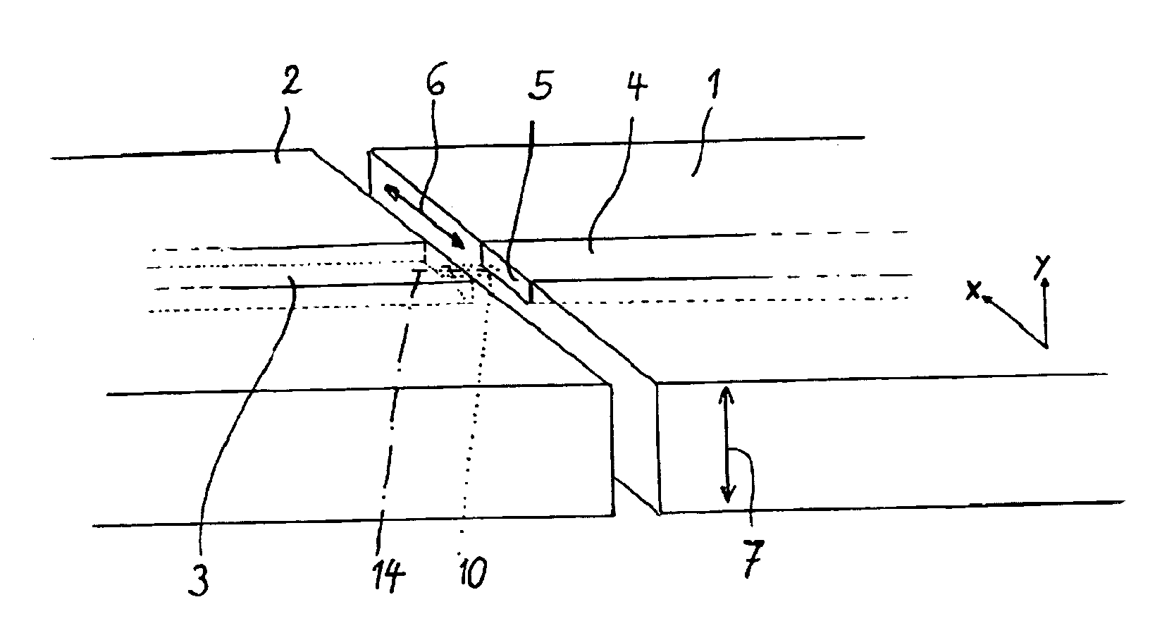
optical fiber down to the dimensions of on chip high-index contrast waveguides and of having to precisely align the position of the optical fiber relative to the semiconductor chip.
A similar problem arises when directly coupling a semiconductor laser chip containing a laser diode to a primary photonic chip containing other optical devices such as single mode waveguides or modulators.
However, such grating couplers also induce other constraints.
For one, such coupling schemes often only work for one polarization, or when they work for two polarizations they create additional complications such as the necessity of two photonic chip waveguides with uneven coupling from the fiber to the two waveguides depending on the state of polarization of the light.
These methods are also poorly suited for direct coupling from a laser diode to a primary photonic chip, since the dimensions of the laser beam are significantly smaller than the grating coupler dimensions in at least one dimension, as the typical dimension of the laser beam in the direction perpendicular to the laser diode chip surface is on the order of 1 μm and typical grating coupler dimensions are of at least several microns.
However, constraints relative to uneven coupling depending on polarization and stringent alignment tolerances remain.
Constraints relating to stringent alignment tolerances are difficult to satisfy and lead to high manufacturing costs not only because the alignment has to be established during assembly, but also because alignment has to be maintained after assembly, thus requiring very stable and reliable optical packaging solutions and leading to yield fallout.
However, this method suffers from the fact that alignment tolerances are directly determined by the dimensions of the waveguide cross-section at the chip interface and are typically sub-micron for high index contrast waveguides.
Also, assembly can be complicated due to the fact that the edge of the chip offers very little area to permanently attach a fiber or a laser, as opposed to the chip surface in the prior methods that allow permanently gluing a fiber, fiber array, laser diode, laser submount or optical bench to the chip surface.
This is a very costly packaging technology.
While it is straightforward to widen the waveguide in the direction along the chip surface, by simply drawing a wider lithographically defined waveguide, it is much more difficult to taper a waveguide in the vertical direction perpendicular to the photonic chip surface since in the latter case the dimensions are determined by the dimensions of deposited thin film layers.
Thin films typically used in semiconductor chips, such as silicon, poly-silicon or silicon oxi-nitrides in the case of silicon based photonics are both difficult to fabricate with slanted cross-sections for tapering in the vertical direction and to deposit in thick enough layers to match an optical fiber cross-section.
This method can result in technical constraints.
This complicates manipulation of the laser diode as it has to be electrically contacted and it constrains the alignment process as the diode has to remain cold enough in order to be operated.
However, this tolerance remains too high to passively butt-couple a typical semiconductor laser to a high index contrast waveguide.
In this case, a misalignment by 1 or a few microns in the horizontal direction due to the tolerance of a passively aligned pick-and-place system very adversely effects the coupling efficiency between the laser diode and a waveguide located on the primary photonic chip.
Tapering the horizontal dimension to a much wider width than the width of the laser beam significantly relaxes the required alignment tolerance, but also reduces the coupling efficiency obtained under optimum coupling conditions if the laser beam width is not increased accordingly, hence there is a trade-off between the peak coupling efficiency and the required alignment tolerance.
This is caused by the fact that widening of the waveguide without widening of the laser beam results in a mode overlap mismatch that reduces the coupling efficiency in a single mode system, i.e., in a system where the coupled to waveguide on the primary photonic chip is single mode for at least a portion of its path.
This approach is however limited both by technical and economic considerations.
Filamentation can result in a complex laser beam profile that can also change over time, both of which prevent efficient coupling of the laser beam into single mode photonic waveguides on the primary photonic chip.
Widening the laser strip in conventional technology can also be difficult since it can make it harder to efficiently and homogenously electrically pump the laser beam.
Other methods to increase the width of the laser beam, such as tapering the laser strip close the edge of the laser chip typically results in increased manufacturing cost.
Since the optical gain material on the laser diode chip results in high optical losses when it is not pumped, and since pumping it efficiently in the broadened laser strip region is both technically challenging and leads to excess current consumption, it is typically necessary to selectively remove the laser gain material in the tapered region and to selectively regrow another material in its stead.
This is a very expensive and typically poorly yielding process.
In practice, however, the vertical alignment accuracy is limited by the attachment process.
However, they also require ultra planar surfaces on both the laser chip and on the photonic chip.
With these bonding methods electrical contacting between the top surface of the laser chip and the top surface of the photonic chip is also complex since the adhesion does not occur via a conductive layer.
They result however in degraded vertical alignment accuracy on the order of a few 100 nm, since the bonding layer can get more or less compressed.
At the extreme, controlled collapse bump bonding is very tolerant to high particle count (dust) and non-planar topographies, but results in very poor vertical alignment control, with tolerances of at least one to several micrometers.
As with horizontal alignment tolerances, this alignment tolerance relaxation method is limited by the fact that a vertical waveguide dimension substantially larger than the vertical laser beam dimension leads to reduced overlap and reduced peak coupling efficiency.
The difficulty in coupling to a single mode waveguide located on a primary photonic chip from an incoming input light beam external to the primary photonic chip results from the reciprocity principle.
A misalignment of the input beam on the same order than the full width at half maximum of the input beam will thus lead to a substantial reduction of coupling efficiency if the input beam is well matched to the waveguide mode.

Method used


Image

  • Laser to Chip Coupler
  • Laser to Chip Coupler
  • Laser to Chip Coupler

Examples


Embodiment Construction

[0060]In a first aspect several waveguides are routed to the interface of the primary photonic chip in a manner such that they can collect light from an input beam provided by the second optical element. At the chip interface, the array of waveguides typically cover a width that is wider than the input beam so as to fully collect the input beam and to provide some margin for lateral (horizontal) displacement of the input beam.

[0061]Independent waveguides are defined as being separated with a sufficient distance from each other such that the coupling between adjacent independent waveguides is negligible. For a silicon waveguide of dimensions 400 nm width by 200 nm height this distance is for example typically on the order of 1 to 2 microns. In an array of independent waveguides the area coverage of waveguide cores in the cross-section of the array is relatively low, so that if such an array were to collect light from an input beam, only a small portion of the light from the input bea...


PUM

PropertyMeasurementUnit
widthaaaaaaaaaa
lengthaaaaaaaaaa
lengthaaaaaaaaaa

Abstract

A method and an apparatus for butt-coupling an input beam incoming from a photonic device of a second optical element to a primary photonic chip at an input interface of the primary photonic chip is disclosed. The primary photonic chip comprises a coupling apparatus. The light from the input beam is butt-coupled to the coupling apparatus. The coupling apparatus comprises a plurality of more than one single mode optical paths on the primary photonic chip. The single mode optical paths are strongly coupled to each other at the input interface of the primary photonic chip. Regions of strongly coupled single mode optical paths can correspond to one or both of distinct but highly coupled waveguides or waveguides fully merged into a multi-mode section.

Description

CROSS-REFERENCE TO RELATED APPLICATIONS[0001]This application is the U.S. National Phase of International Application No. PCT / EP2011 / 067938, filed Oct. 13, 2011, claiming benefit of U.S. Provisional Patent Application No. 61 / 393,170, filed Oct. 14, 2010, U.S. Provisional Patent Application No. 61 / 437,672, filed Jan. 30, 2011, and U.S. Provisional Patent Application No. 61 / 442,178, filed Feb. 12, 2011, the contents of which are hereby incorporated by reference in their entirety as part of the present disclosure.FIELD OF THE INVENTION[0002]This invention relates to an apparatus enabling the attachment of a primary photonic chip to a second optical element such as a semiconductor laser chip, a planar lightwave circuit or another photonic chip, with low manufacturing costs and high optical coupling efficiency between the primary photonic chip and the second optical element.[0003]In particular this apparatus can relax alignment tolerances required to achieve high optical coupling efficie...

Claims


Application Information

Patent Timeline
Patent Type & Authority Applications(United States)
IPC IPC(8): G02B6/125G02B6/13
CPCG02B6/12007G02B6/2813G02B6/305G02B6/34G02B6/42Y10T29/49826H01S5/02252H01S5/0228G02B6/125G02B6/13G02B6/423H01S5/0225H01S5/02326
Inventor WITZENS, JEREMY
Owner RWTH AACHEN UNIV
Why Eureka
Try Eureka