
Dielectric ceramic composition and electronic device

a technology of ceramic composition and electronic device, which is applied in the direction of fixed capacitors, basic electric elements, electrical apparatus, etc., can solve the problems of reduced effective capacitance under used environment, rapid reduction of specific permittivity, and different problems affecting the ferroelectricity of ceramic composition, etc., and achieve good insulation resistance and good characteristics

Active Publication Date: 2013-08-29
TDK CORPARATION
View PDF3 Cites 2 Cited by
  • Summary
  • Abstract
  • Description
  • Claims
  • Application Information

AI Technical Summary

Benefits of technology

The present invention provides a dielectric ceramic composition that has good insulation resistivity and can withstand high electric field intensity. The composition contains a tungsten bronze-type structured compound with high mole ratio of "A" element and "RE" element to "B" element. The compound shows paraelectric behavior and has a relatively high specific permittivity even at high field intensity. This makes the ceramic composition better suited for high-performance electronic applications than traditional ferroelectrics like barium titanate.

Problems solved by technology

However, when electronic device having dielectric layer of ferroelectrics is used under a high rated voltage, namely, when it is used under a high field intensity, various problems due to ferroelectricity of the ceramic composition were caused.
For instance, there was a problem that specific permittivity rapidly decreases as field intensity increases; and as a result, effective capacitance under used environment decreases.
In addition, there was a problem that cracks or noises due to electrostriction generate.
There was also a problem such as a deterioration of capacitance change rate with respect to temperature.
However, although said insulation resistance can be controlled by controlling firing atmosphere, there were problems such as a matter of facilities and processes.

Method used

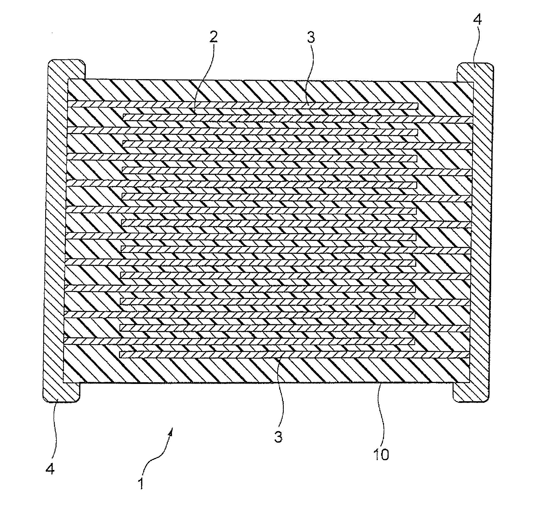
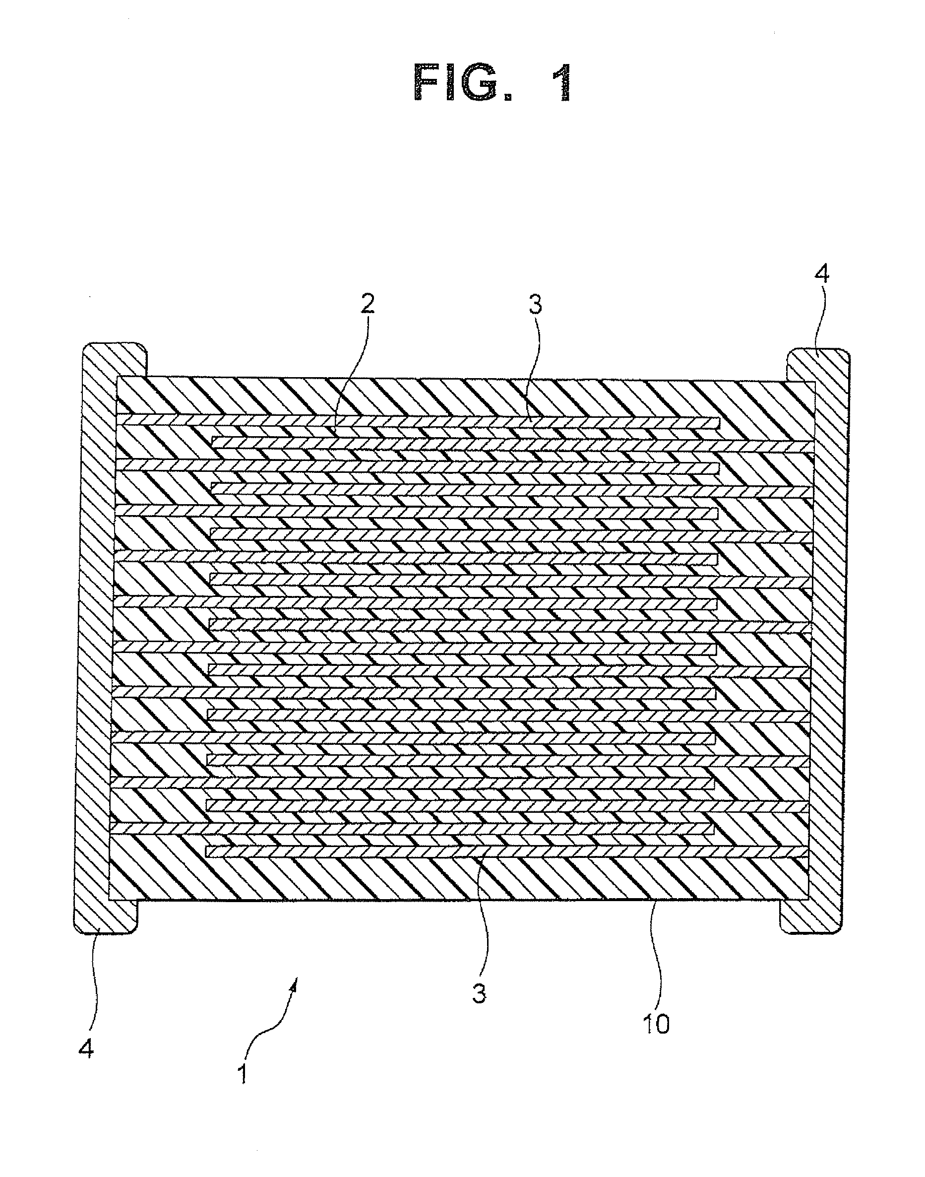

Image

  • Dielectric ceramic composition and electronic device
  • Dielectric ceramic composition and electronic device

Examples


example 1

[0059]At first, a compound powder shown by a general formula {A1−x(RE)2x / 3}y-B2O5+y was prepared, and this was determined as dielectric raw materials. In the general formula, “A” element is Ba, “RE” element is La, “B” element is Nb, “x” is 0.40 and “y” is the values shown in Table 1.

[0060]Next, ion-exchange water and polyvinyl alcohol were poured in a container, mixed for 2 hours at 85° C., and then polyvinyl alcohol aqueous solution was obtained. Concentration of the aqueous solution was made to 6 wt % by regulating an amount of ion-exchange water.

[0061]20 wt % of polyvinyl alcohol aqueous solution with respect to 100 wt % of the prepared dielectric raw materials was added, mixed and granulated in a mortar, and then granulated powder was obtained. The obtained granulated powder was poured into a mold of Φ11.1 mm, press formed under a pressure of 10 kg / cm2, and then a disk-shaped green compact was obtained.

[0062]Next, the obtained green compact was fired in air and a disk-shaped sin...

example 2

[0077]Samples of ceramic capacitor were manufactured in the same way as sample 2 of Example 1, except using a mixture of a powder of the compound used in example 1 and an oxide powder shown in Table 2 as dielectric raw materials. And then the same evaluation as example 1 was performed. Results are shown in Table 2.

[0078]Note that oxide powder content of each samples 20 to 24 was set to be 1.0 mole in terms of element with respect to 100 moles of a compound. Further, a total content of V oxide and Mn oxide in sample 25 was set to be 1.0 mole in terms of element with respect to 100 moles of the compound.

TABLE 2characteristics of a sintered bodyFiringContractionInsulation(Ba1−xLa2x / 3)yNb2O5+yOxideTemperatureRatioSpecificResistivitySamplesxyKind[° C.][%]Permittivity[Ω· m]20.401.002none130017.53901.2E+12200.401.002V127518.14111.3E+12210.401.002Fe130018.03741.3E+12220.401.002Mo130018.04131.3E+12230.401.002W130018.33991.2E+12240.401.002Mn130018.04051.2E+12250.401.002V, Mn127518.64021.3E+12...

example 3

[0080]Samples of ceramic capacitor were manufactured in the same way as sample 20 of Example 2, except V oxide content is as shown in Table 3. Results are shown in Table 3. Note that “y” values of samples 26 to 28 are shown in table 3.

TABLE 3characteristics of a sintered bodyOxideContractionInsulation(Ba1−xLa2x / 3)yNb2O5+yContentRatioSpecificResistivityDC-BiasSamplesxyKind[mol][%]Permittivity[Ω· m](20 V / μm)20.401.002—17.53901.20E+12−2%20a0.401.002V0.0117.53951.22E+12−2%20b0.401.002V0.0517.64021.25E+12−2%20c0.401.002V0.518.04051.28E+12−2%200.401.002V1.018.14111.30E+12−2%20d0.401.002V2.518.33901.35E+12−2%20e0.401.002V5.018.43701.28E+12−2%20f0.401.002V7.018.52901.25E+12−2%260.401.010V1.017.4360 1.2E+12−2%270.401.300V1.016.5170 1.2E+12−1%280.401.500V1.015.337 1.4E+12 0%“mE+n” indicates “m × 10n”

[0081]From table 3, it was confirmed that V oxide content is preferably within a range of 0.05 to 5 mol %. Further, good values could be obtained even when “y” value changed. Note that content of ...


PUM

PropertyMeasurementUnit
mole ratioaaaaaaaaaa
holding temperatureaaaaaaaaaa

Abstract

Dielectric ceramic composition comprising a compound shown by a general formula {A1−x(RE)2x / 3}y-B2O5+y and has a tungsten bronze-type structure. In the formula, “A” is at least one selected from a group comprising Ba, Ca, Sr and Mg, “B” is at least one selected from Nb and Ta, “RE” is at least one selected from Sc, Y, La, Ce, Pr, Nd, Sm, Eu, Gd, Tb, Dy, Ho, Er, Tm, Yb and Lu, and said “x” and “y” satisfies 0<x<1 and y>1.000, respectively. The dielectric ceramic composition further comprises an oxide of at least one selected from V, Mo, Fe, W, Mn and Cr.

Description

BACKGROUND OF THE INVENTION[0001]1. Field of the Invention[0002]The present invention relates to a dielectric ceramic composition and electronic device wherein said dielectric ceramic composition is applied to its dielectric layer. More precisely, the present invention relates to a dielectric ceramic composition having good characteristics under a high electric field intensity, and to an electronic device, wherein said dielectric ceramic composition is applied to dielectric layer, having an electrode.[0003]2. Description of the Related Art[0004]In recent years, a demand for a high reliability of electronic device is high. For instance, size reduction and high performance of multilayer ceramic capacitor, an example of electronic device, is rapidly processing; while its use is expanding. As a result, various characteristics are required for such capacitors.[0005]Conventionally, ceramic composition showing ferroelectricity (ferroelectrics), such as barium titanate, is often used for di...

Claims


Application Information

Patent Timeline
Patent Type & Authority Applications(United States)
IPC IPC(8): C04B35/50H01G4/12H10N30/853
CPCC04B35/495H01G4/30C04B2235/3208C04B2235/3213C04B2235/3215C04B2235/3224C04B2235/3225C04B2235/3227C04B2235/3229C04B2235/3239C04B2235/3241C04B2235/3251C04B2235/3256C04B2235/3258C04B2235/3262C04B2235/3272C04B2235/76C04B2235/79C04B2235/9615C04B35/50H01G4/1254C04B2235/3206
Inventor IGUCHI, TOSHIHIROYOSHII, AKITOSHIKOJIMA, TATSUYATAKAGI, SATOSHI
Owner TDK CORPARATION
Learn More