Methods of manufacturing photovoltaic electrodes

a photovoltaic electrode and manufacturing method technology, applied in the manufacture of final products, basic electric elements, electrolytic capacitors, etc., can solve the problems of low efficiency of p-type metal oxides, limited effectiveness of tandem dsscs, inefficient light absorption capability, etc., to achieve better electrodes, high porosity, and high light absorption.

Inactive Publication Date: 2013-08-29
UNIV COLLEGE DUBLIN NAT UNIV OF IRELAND DUBLIN
View PDF8 Cites 0 Cited by
  • Summary
  • Abstract
  • Description
  • Claims
  • Application Information

AI Technical Summary

Benefits of technology

[0017]It has been found that one obtains a significantly better electrode using this method when compared to thermal sintering. Improvements have been found in the physical characteristics of the nanoparticle layer, its adhesion and electrical connectivity with the substrate, and the degree of dye absorption. In particular, it is found that the electrodes produced by this method have a surface exhibiting high porosity without sacrificing the mechanical stability of the resulting coatings. This surface morphology ensures higher light absorption by the monolayer of adsorbed dye, while keeping an intimate contact between the particulate material and the dye molecules. This in turn reduces the inner resistance and hence improves the charge injection efficiency.
[0018]It is hypothesized that the advantages of the invention can be attributed to a number of factors including the rapidity of heating and the bulk homogeneity of heating due to the materials interacting with “cold” microwaves coupled through a plasma instead of radiant heat in a conventional furnace. This avoids the outer surface “cooking”, i.e. a heat-affected outer zone which can hinder dye absorption, and it increases the adhesion between sintered particles and the underlying substrate relative to conventionally sintered electrodes. Details of the results will be given below.
[0019]The net result is that electrical properties of the photovoltaic electrodes prepared according to this method are significantly improved (i.e. in some instances ten-fold or more) relative to the equivalent thermal sintered electrodes.

Problems solved by technology

The efficiency, however of p-type metal oxides is still very low, which limits their effectiveness in tandem DSSCs.
Amongst the potential reasons highlighted for the poor conversion efficiency of the cathode within tandem DSSC, the more critical are the inefficient light absorption capability, poor charge injection efficiency and charge transport rate, along with inner resistance.
A disadvantage with thermal sintering is the processing time.
Further disadvantages with conventional thermal sintering include the photovoltaic performance of photocathodes produced according to this method and the probably related physical shortcomings of such photocathodes, such as the adhesion between the substrate and the nanoparticular NiOx layer, the post-sintering average particle size, the pore characteristics, and the dye absorption.

Method used


Image

  • Methods of manufacturing photovoltaic electrodes
  • Methods of manufacturing photovoltaic electrodes
  • Methods of manufacturing photovoltaic electrodes

Examples


example 1

NiOx Nanoparticles on FTO Glass Substrate

[0065]Sample Preparation

[0066]In order to prepare photovoltaic electrodes, fluorine doped tin oxide (FTO) glass substrates (3 mm thick) supplied by Mansolar. The glass substrates (2×2 cm) were ultrasonically cleaned in propanol followed by acetone, each for 5 minutes. Other typical substrates which may be used include indium doped tin oxide (ITO) glass and polymers e.g. PET.

[0067]A deposition layer medium was made, comprising NiOx nanoparticles (˜50 nm) suspended in methanol (20 mg / ml) as a dispersion medium. This deposition layer medium was deposited by spraying using a nebulizer (Burgener Mira Mist atomizer) which uses an inert gas to break up the suspension into small aerosol droplets. In this case, the inert gas used was nitrogen at a flow rate of about 2 litres / min. The nebulizer was moved over the surface of the substrate in a raster pattern using a computer numeric control (CNC) device with a line speed of 20 mm / s and a step interval o...

example 2

TiO2 Nanoparticles on Flexible Polymeric Substrate

[0097]Sample Preparation

[0098]Degussa P25 TiO2 nanoparticles with an average size between 20-25 nm were deposited on ITO-PEN coated substrate (where ITO stands for indium doped tin oxide and PEN for polyethylene naphthalate). The TiO2 was prepared in a suspension form by grinding the nanoparticles powder in an alumina mortar in order to breakdown the agglomerated particles. The ground paste was then transferred into a recipient using methanol solvent vehicle and diluted to a final concentration of 25-30 mg / ml and further sonicated using a sonication horn probe.

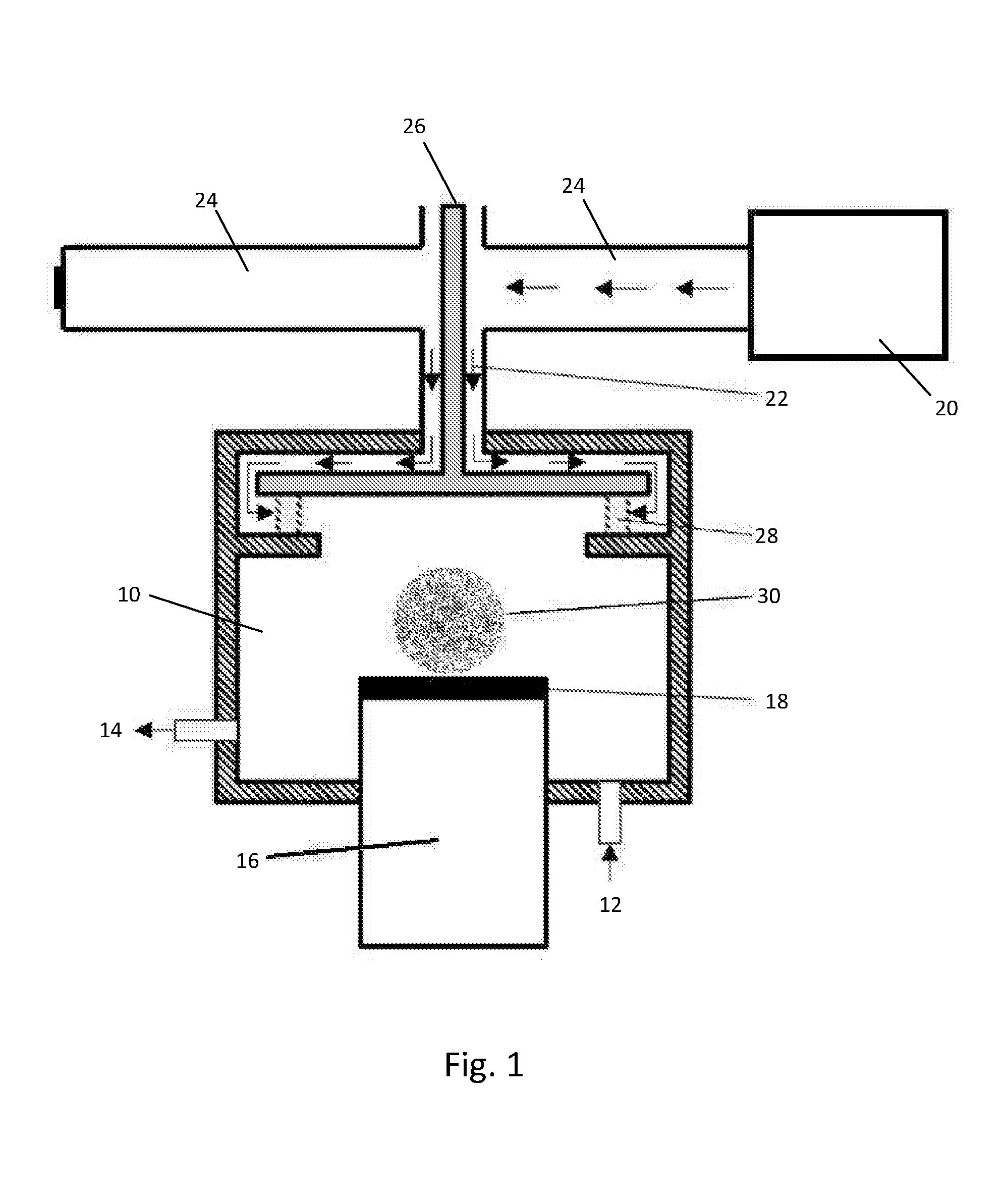
[0099]The TiO2 suspension was applied to the plastic substrate using a roll-to-roll spraying technique. In this technique the suspension is pumped through a nebulizer, shown in FIG. 11, and with the assistance of a pressurised gas (nitrogen) is atomised and projected at the surface of the plastic substrate mounted onto a CNC controlled (X-Y-Z) pneumatic table.

[0100]In addition ...


PUM

PropertyMeasurementUnit
particle sizeaaaaaaaaaa

Abstract

A photovoltaic electrode is made by the following steps: (a) depositing on a substrate a dispersion comprising powdered semiconductor particles in a dispersion medium; (b) removing the majority of the dispersion medium to leave the powdered semiconductor particles in a deposition layer on the substrate; (c) creating a plasma using microwave energy excitation; (d) exposing the deposition layer to said microwave-excited plasma for a sufficient time to sinter the nanoparticles thereby adhering them to the substrate; and (e) absorbing a dye into said sintered deposition layer. The electrode thus obtained exhibits improved performance relative to conventional sintered electrodes.

Description

TECHNICAL FIELD[0001]This invention relates to the manufacture of photovoltaic electrodes, and in particular to the manufacture of dye-sensitized solar cells.BACKGROUND ART[0002]Dye-sensitized solar cells (DSSCs) show considerable potential as a relatively low cost alternative to silicon based solar cells. These cells were developed by Gratzel and co-workers in 1991 [B. O'Regan, M. Gratzel, Nature, 353 (1991) 737-740] and there is currently a considerable focus on enhancing their light conversion efficiency and stability.[0003]The principal components of a DSSC electrode are a conducting substrate, which is usually a transparent conductive oxide coated on glass, a highly porous layer of semiconductor material, and a photosensitive dye absorbed into and coating the porous semiconductor.[0004]In the case of conventional DSSCs, dye sensitization involves solely the semiconductor anode made of n-type TiO2 nanoparticles. The counter electrode is generally a metallic cathode with no photo...

Claims


Application Information

Patent Timeline
Patent Type & Authority Applications(United States)
IPC IPC(8): H01L31/0224
CPCH01G9/2031H01L31/022425Y02E10/542H01G9/2059Y02P70/50
Inventor DOWLING, DENISAWAIS, MOHAMED
Owner UNIV COLLEGE DUBLIN NAT UNIV OF IRELAND DUBLIN
Why Eureka
Try Eureka