Method for fabricating field emission cathode, field emission cathode thereof, and field emission lighting source using the same

a field emission cathode and lighting source technology, applied in the manufacture of electrode systems, electric discharge tubes/lamps, discharge tubes luminescnet screens, etc., can solve the problems of high cost, difficult to mass produce field emission lighting sources, and high instrument costs used in this process, so as to improve field emission characteristics and reduce labor costs. , the effect of high fractional yield

Active Publication Date: 2014-02-27
NATIONAL DEFENSE UNIVERSITY
View PDF2 Cites 5 Cited by
  • Summary
  • Abstract
  • Description
  • Claims
  • Application Information

AI Technical Summary

Benefits of technology

[0046]By using the method for fabricating field emission cathode of the present disclosure, which utilizes the amphipathic characteristic (hydrophilic and non-hydrophilic) of the organic noble metal catalyst or the co-alloying of replacing the metal of the cathode substrate with the noble metal catalyst, the noble metal catalyst can be bounded with the field emission cathode substrate. Additionally, by performing the deposition of the noble metal catalyst and the pyrolysis of the carbon source gas in a high temperature and a vacuumed environment by using TCVD, the nano carbon materials can be grown which catalyzed by the noble metal catalyst. Due to the great dispersity of the noble metal catalyst depositing on the field emission cathode substrate, namely unlikely to be aggregated, high density coiled nano carbon materials, including coiled carbon nano tubes and coiled carbon nano fibers, with single or specific fractional yield can be fabricated by using different operation conditions, thereby overcoming the limitation and low fractional yields of growing coiled carbon nano tubes and coiled carbon nano fibers in prior art.
[0047]The present disclosure provides the method for fabricating field emission cathode, and the field emission cathode fabricated by the method, the surface of the field emission cathode can geminate and grow coiled nano carbon materials with high fractional yield, so that the coiled carbon nano tubes and the coiled carbon nano fibers have more nano corners than chained CNT made by using conventional methods. These nano corners are like the end tip of carbon nano tubes, which are capable of emitting electrons therefrom. While applying an electric field to the field emission cathode, the coiled nano carbon materials can be emitted with much more electron beams, thereby forming a mo...

Problems solved by technology

This process for fabricating CNT directly by using CVD, however, needs to be processed in a high temperature environment, and those instruments used in this process are expensive.
Additionally, using this process to mass produce the field emission lighting source is quite difficult and is not cost-effective.
Moreover, the carbon nano tube is linear-shaped, electrons can only be emitted from the tip end thereof, and the emitting area is then limited accompanying with the melting of the carbon nano tube, so that the luminous quantity is low, thereby limiting the range of its applications.
Therefore, while fabricating the field emission lighting source, the organics will gradually leak during vacuum packaging and ion bombard, thus influencing the working life and the service luminous efficiency of the field emission lighting source.
However, in this manner, a traditional composited plating process was used, the plating solution thereof is easy to decompose and is hard to be storage.
Plus, the emission efficiency and the luminance uniformity of the field emission lighting source merely using the carbon nano tube for field emission was too low to be used widely.
Among these prior arts, even the carbon nano fiber had better field emission characteristics than the carbon nano tube, the fractional yield of ...

Method used


Image

  • Method for fabricating field emission cathode, field emission cathode thereof, and field emission lighting source using the same
  • Method for fabricating field emission cathode, field emission cathode thereof, and field emission lighting source using the same
  • Method for fabricating field emission cathode, field emission cathode thereof, and field emission lighting source using the same

Examples


first embodiment

The First Embodiment

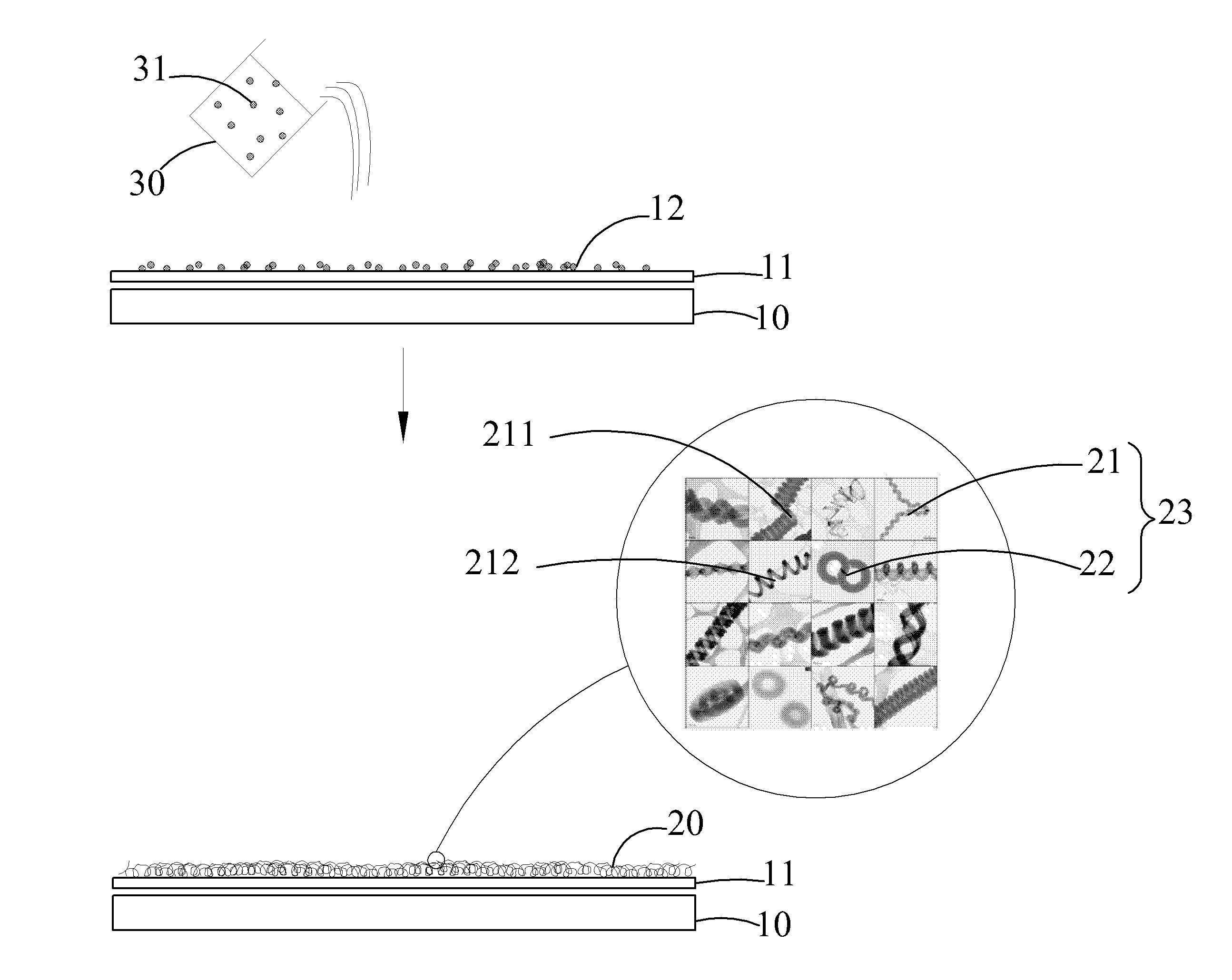
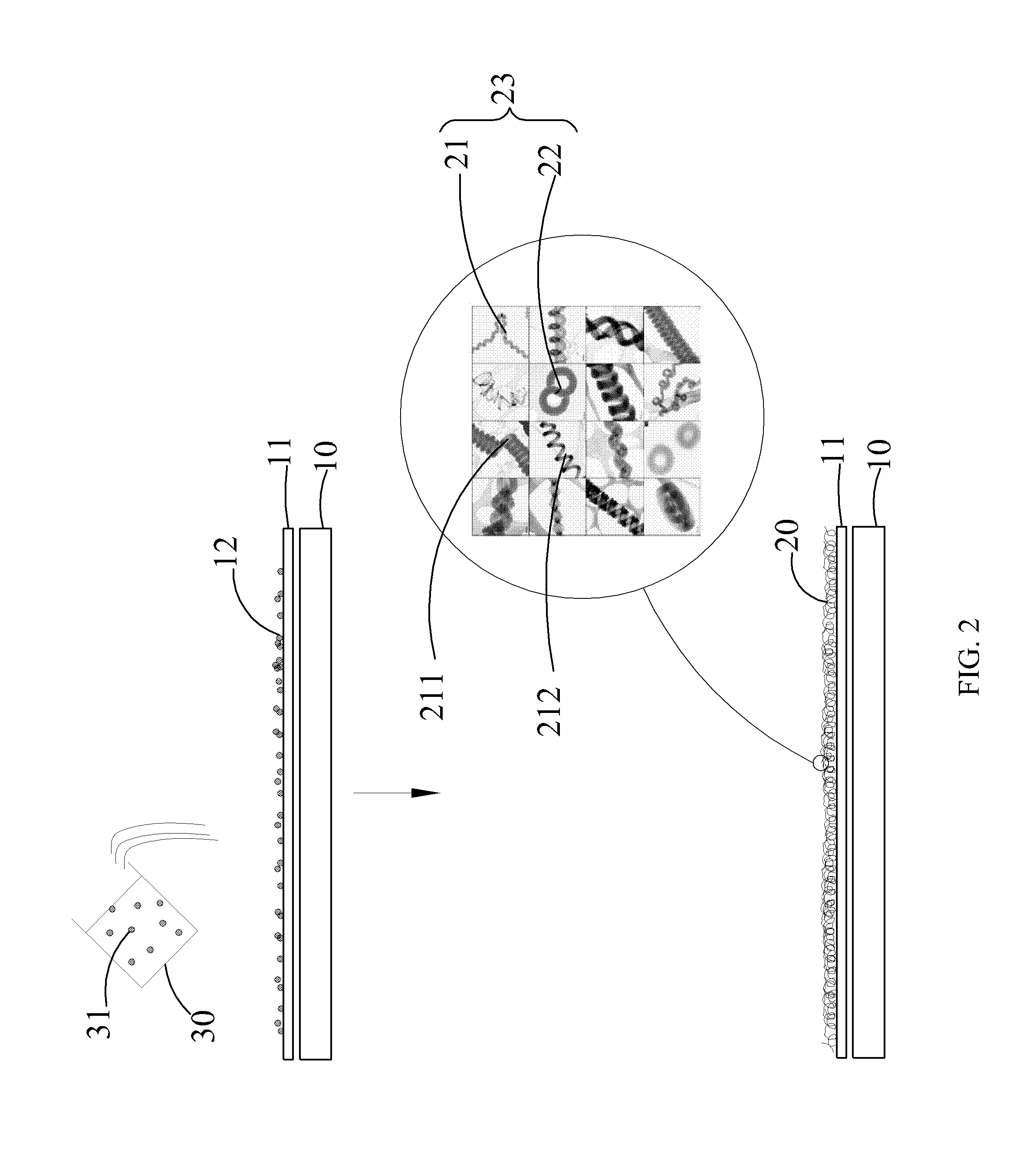
[0107]In the present embodiment, the method for fabricating field emission cathode 4 of the present disclosure utilizing different predetermined growth temperature Tk is performed. The material of the cathode substrate 10 utilized in the present embodiment is majorly made of iron-cobalt-nickel alloy (#304 stainless steel) metal filament. The metal filament is first cleaned by physical sand blasting, then a metal conductive layer 11 is electroless plated on the metal filament. The metal conductive layer 11 of the cathode substrate 10 is washed, cleaned, and rinsed with acetone and water, and then dried (refer to step S1). The electroless plated metal filament (cathode substrate 10) is subsequently immersed in the noble metal catalyst solution 30 for 20 min (refer to step S2), where a compound of palladium chelated copolymer of styrene monomer and N-isopropylacrylamide monomer (Pd(styrenea-co-NIPAAmb)) is used as the organic chelated noble metal catalyst 31 of the ...

second embodiment

The Second Embodiment

[0113]In the present embodiment, the method for fabricating field emission cathode 4 of the present disclosure utilizing different predetermined growing time is performed. The material of the cathode substrate 10 utilized in the present embodiment is majorly made of iron-cobalt-nickel alloy (#304 stainless steel) metal filaments, where the cathode substrate 10 is first cleaned by physical sand blasting, and then a metal conductive layer 11 with nickel is electroless plated on the metal filaments; the metal conductive layer 11 is washed, cleaned, and rinsed with acetone and water, and then dried (refer to step S1). The nickel plated metal filaments (cathode substrate 10) is subsequently immersed in the noble metal catalyst solution 30 for 20 min (refer to step S2), where a compound of palladium chelated copolymer of styrene monomer and N-isopropylacrylamide monomer (Pd(styrenea-co-NIPAAmb)) is used as the organic chelated noble metal catalyst 31 of the noble meta...

third embodiment

The Third Embodiment

[0117]In the present embodiment, the method for fabricating field emission cathode 4 of the present disclosure utilizing different predetermined growth temperature Tk is performed. The material of the cathode substrate 10 utilized in the present embodiment is majorly made of iron-cobalt-nickel alloy (#304 stainless steel) metal filaments, where the cathode substrate 10 is first immersed in 10% HCl for 30 seconds, following by washing with water, and then dried (refer to step S1); the metal filament (cathode substrate 10) is subsequently immersed in the noble metal catalyst solution 30 for 30 min to 60 min (refer to step S2), where PdCl2 is used as the noble metal catalyst 31 of the noble metal catalyst solution 30, and the concentration of the PdCl2 is ranged from 300 ppm to 1500 ppm, which depends on the metal filament immersing time. Next, the metal filaments (cathode substrate 10) is placed in the atmosphere chamber and dried in 100° C., the remained moisture ...


PUM


Abstract

A method for fabricating field emission cathode, a field emission cathode, and a field emission lighting source are provided. The method includes: forming a catalyst crystallite nucleus layer on the surface of cathode substrate by self-assembly of a noble metal catalyst, growing a composited nano carbon material on the cathode substrate by using a TCVD process, in which the composited nano carbon material includes coil carbon nano tubes and coil carbon nano fibers. The measured quantity of total coil carbon nano tubes and coil carbon nano fibers is higher than 40%. The field emission cathode is fabricated by the aforementioned method, and the field emission lighting source includes the aforementioned field emission cathode.

Description

CROSS-REFERENCE TO RELATED APPLICATION[0001]This application claims the benefit of Taiwan Patent Application No. 101130516, filed on Aug. 22, 2012, in the Taiwan Intellectual Property Office, the disclosure of which is incorporated herein in its entirety by reference.FIELD OF THE INVENTION[0002]The present invention relates to a method for fabricating field emission cathode, a field emission cathode thereof, and a field emission lighting source using the same, particularly to a method for fabricating field emission cathode, which utilizes a noble metal catalyst for growing a composited nano carbon material, and more particularly packing the field emission cathode and a field emission anode having a phosphor layer in a light-transmissive vacuum envelope in order to assembly a field emission lighting source.BACKGROUND OF THE INVENTION[0003]A theory of field emission was first discovered by R. H. Fowler and L. W. Nordheim in 1928; by applying a strong electric field between a field emi...

Claims


Application Information

Patent Timeline
IPC IPC(8): H01J1/304
CPCH01J1/304B82Y99/00Y10S977/939B82Y40/00H01J9/025H01J63/02H01J63/06H01J2201/3043H01J2201/30434H01J2201/30469
Inventor GER, MING-DERPU, NEN-WENLIU, YIH-MINGCHUNG, KUN-JU
Owner NATIONAL DEFENSE UNIVERSITY
Why Eureka
Try Eureka