Surface Engineering of Thermoplastic Materials and Tooling

a thermoplastic material and tooling technology, applied in the direction of manufacturing tools, non-metal conductors, conductors, etc., can solve the problems of thermoset composite materials, limited overall production rate of structural components, and difficult imprinting of thermoplastic resin compositions into fiber reinforcing materials

Inactive Publication Date: 2014-04-24
CYTEC IND INC
View PDF1 Cites 29 Cited by
  • Summary
  • Abstract
  • Description
  • Claims
  • Application Information

AI Technical Summary

Benefits of technology

[0023]The present invention provides a prepared mold tool having a releasably adhered surface layer polymer coating on the mold surface of the mold tool. The mold tool is a non-porous metal mold tool having a mold surface with a texture and a release film adhered to the textured mold surface of the mold tool and the surface layer polymer coating adhered to the release film. The surface layer polymer coating is preferably a plurality of thermoplastic particles applied to the mold surface by plasma spray creating a substantially fused layer of thermoplastic particles. The prepared mold tool aids placement and adhesion of the first ply of a fiber reinforced thermoplastic composite material such as a thermoplastic prepreg, a thermoplastic unidirectional tape or web, fiber tow / preg, or fabric, or non-woven materials such as a mat or veil. Thermoplastic prepregs are traditionally applied by hand lay-down while thermoplastic unidirectional tapes are applied by in situ automated laydown tape placement against a mold tool.

Problems solved by technology

Thermoset composites suffer from disadvantages including processing problems concerned with removing entrained air or volatiles so that a void-free matrix is produced.
The overall production rate for a structural component is limited by the lengthy cure in the autoclave process step and related operations to prepare the material for that process step.
Thermoplastic resin compositions are more difficult to impregnate into the fiber reinforcing material because of their comparatively higher viscosity than thermosetting resin compositions.
Consequently, it is problematic to make the thermoplastic composite tape adhere to complex mold surfaces during the lay-up process.
Whilst both proposed solutions allow the first layer of thermoplastic composite tape to be successfully applied to complex shaped mold surfaces, they introduce their own problem of how to subsequently remove the formed composite component from the mold when the laying up process is complete, since the component is now effectively bonded to the mold surface.
This method of fabrication is time consuming and cost intensive, and can possibly result in non-uniformity in the lay-up.
Thermoplastic composite materials lack tack, which complicates the use of hand and automated lay-up operations, especially of the first ply against the molding tool surface.
First ply lay-down of thermoplastic materials is complicated by the lack of tack to hold the first layer down to the tool.
Each of these methods has limitations in cost, tool complexity, variation to the dimensions of the part or requires hazardous solvents to practice.
Thermoplastics generally have low surface energies, a high glass transition temperature (“Tg”), making adhesion at room temperature unlikely.
Furthermore, the high performance thermoplastic matrices are in their glass state at room temperature making the molecular diffusion mechanism for tack virtually impossible.
This process step further reduces the total productivity of the composite part operation.
In general, thermoplastic composites have had limited success to date, due to a variety of factors including high processing temperatures (currently around 400° C.
), high pressures, and prolonged molding times needed to produce good quality laminates.

Method used


Image

  • Surface Engineering of Thermoplastic Materials and Tooling
  • Surface Engineering of Thermoplastic Materials and Tooling
  • Surface Engineering of Thermoplastic Materials and Tooling

Examples


example 1

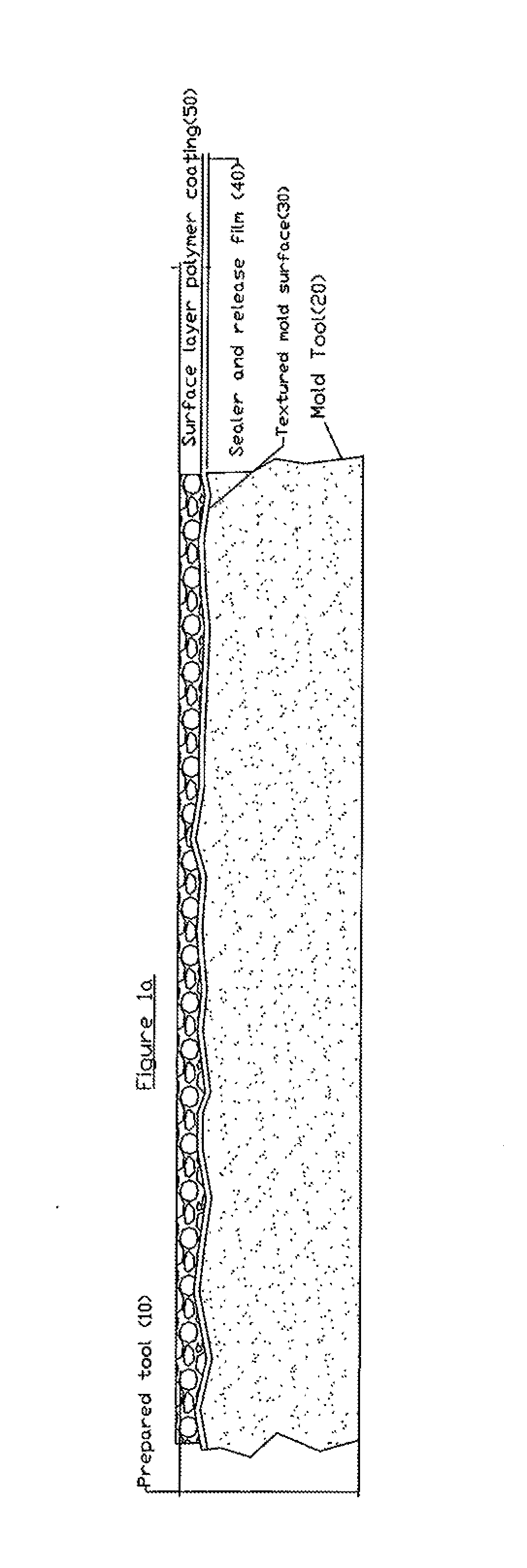
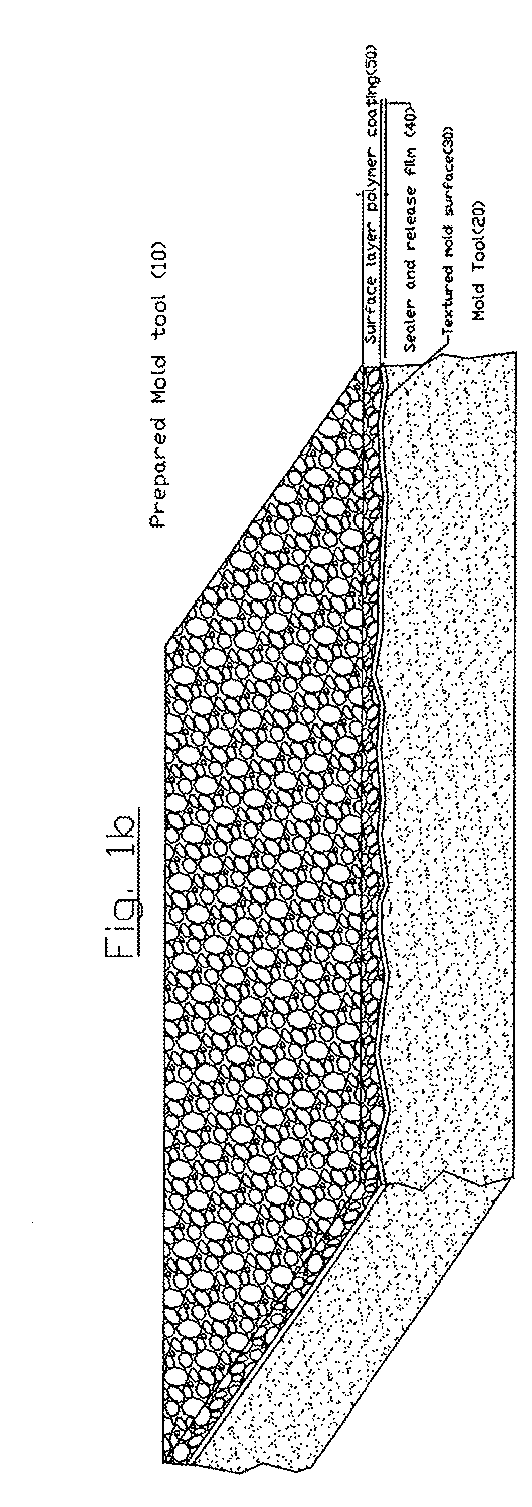
Solvent Based PEI Polymer Sprayed Solution Applied to Tool

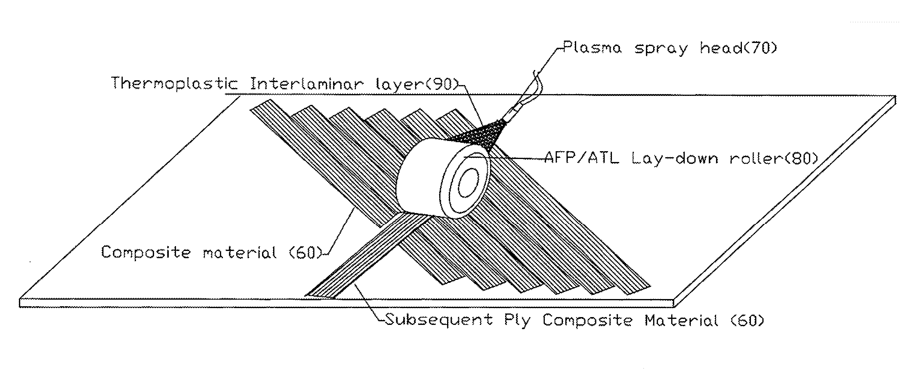
[0095]A formulation of PEI polymer, GE Ultem 1000P at 10% plus Dioxilane at 90% was plasma sprayed onto the mold surface of a steel mold tool which had a release film using an HVLP applicator.

[0096]To test the transfer of the PEI / Dioxilane first ply lay-down fiber reinforced thermoplastic composite, an 8 ply quasi-isotropic panel was created using APC PEKK / AS-4 uni-tape material. The panel was processed with a caul plate at an autoclave temperature of 720° F. (382° C.) and 100 psi of N2. The panel showed some surface anomalies on the coated face.

example 2

Water Based Slurry Hand Applied to Tool

[0097]A direct hand application technique was attempted using a mixture that included surfactant, water, hydrosize (sizing) and thermoplastic, as follows: 1) Sizing 90% / PEKK 10%. 2) D.I water 80% / Surfactant 10% / PEI-Diox. Premix solution 10%. 3) D.I water 80% / Surfactant 10% / PEKK 10%. 4) Sizing 80% / PEI powder 10% / Surfactant 10%). The resulting water based slurry thermoplastic surface layer polymer coating shrank rapidly on the mold surface of the mold tool and did not achieve adequate bonding onto metal mold tool. The surface layer polymer coating flaked off very easily with minimum abrasion.

example 3

PEK Polymer Plasma Sprayed onto Mold Tool

[0098]To impart a coating directly onto the mold surface of a mold tool applied with a sealer and release film, a plasma spray coating was performed using a Praxair SG 100 plasma gun and introduced PEK polymer into the jet stream to heat and accelerate the material to high velocity. Initially there was difficulty maintaining adhesion between the sealed / released tool and the PEK polymer, when the tool was allowed to cool to room temperature, likely caused by the difference in CTE (coefficient of thermal expansion) of the mold tool and the thermoplastic surface layer polymer coating on the smooth mold surface of the mold tool. It appeared that the skin coating released from the tool (Hysol® Frekote® GP sealer agent and release agent Frekote® 800).


PUM

PropertyMeasurementUnit
heightaaaaaaaaaa
diameter D90 sizeaaaaaaaaaa
sizeaaaaaaaaaa

Abstract

A prepared mold tool having a thermoplastic surface layer polymer coating on the mold surface of the mold tool or prepared prepreg having a thermoplastic surface layer polymer coating on the surface of the thermoplastic fiber reinforced prepreg are described that enhance first ply laydown of thermoplastic fiber reinforced composite prepregs onto mold tools for prepreg forming or in situ tape placement. Resulting thermoplastic fiber reinforced composite parts from a thermoplastic fiber reinforced thermoplastic composite material having structural reinforcement fibers with one or more high performance polymers, and a thermoplastic surface layer polymer coating which forms a polymer blend with the high performance polymers of the thermoplastic fiber reinforced composite material thereby imparting improved properties, and methods for making and using same, are provided herein.

Description

BACKGROUND OF THE INVENTION[0001]1. Field of the Invention[0002]The subject matter of the present invention relates to fiber reinforced thermoplastic plastic composite materials and particularly to applying a surface layer polymer coating to a composite forming mold tool or to a fiber reinforced thermoplastic prepreg composite material to enhance the first ply laydown of the prepreg onto the composite forming mold tool for prepreg forming or in situ automated laydown tape placement. In situ application of the surface layer polymer coating during or before automated laydown may also provide a beneficial resin rich interlaminar layer between each layer of fiber reinforced thermoplastic composite material. The surface layer polymer coating is preferably thermoplastic particles applied by plasma spraying to the mold tool or prepreg to form a substantially fused layer of thermoplastic particles. More particularly, in certain embodiments the present invention relates to layered fiber rein...

Claims


Application Information

Patent Timeline
Patent Type & Authority Applications(United States)
IPC IPC(8): B32B7/00B32B7/03
CPCB32B7/005B29C33/56B29C37/0075B29C70/086B29C70/386B32B38/0008B32B2037/268B32B7/03Y10T428/31935B29B15/105B29C70/38B05D1/10B29C33/3842B29C33/42B29C33/62B29C33/68B29K2071/00B29K2079/085B29K2101/12B29K2105/0881
Inventor PRATTE, JAMES FRANCISROGERS, SCOTT ALFRED
Owner CYTEC IND INC
Why Eureka
Try Eureka