Floating filter module and water treatment apparatus and method using the same

a filter module and filter technology, applied in water cleaning, membranes, separation processes, etc., can solve the problems of increasing the cost of processing wastewater, increasing the amount of sewage, wastewater or dirty water, and increasing so as to reduce the risk of damage, improve the filtration rate and filtration duration time, and improve the effect of li

Inactive Publication Date: 2014-05-01
DAEWOONG ECOSYST & SOLUTION
View PDF1 Cites 15 Cited by
  • Summary
  • Abstract
  • Description
  • Claims
  • Application Information

AI Technical Summary

Benefits of technology

[0015]The present invention has been proposed to solve the problem aforementioned, and it is an object of the present invention to provide a floating filter module and a water treatment apparatus and method using it, which are capable of improving filtration rate and filtration duration time by separating and filtering only upper water having relatively low concentration of suspended solids in a wastewater tank.
[0016]It is also another object of the present invention to provide a floating filter module and a water treatment apparatus and method using it, which are capable of reducing of the adhesion amount of micro-pollution particles in a separating and filtering process and removing the adhered micro-pollution particles effectively and quickly when filtration rate is decreased due to adhering of micro-pollution particles.

Problems solved by technology

Environmental pollution like soil and air contaminations and global warming is becoming increasingly serious, and the amount of sewage, wastewater or dirty water (hereinafter referred to as the “wastewater”) has been greatly increased.
As a result, treatment facilities have been developed highly and the cost for processing wastewater is on the increase.
Moreover, various water pollutants are not processed perfectly and can be introduced into rivers or rakes which may be used as source water.
Therefore, it is difficult to manage the quality of water effectively.
Thus, there is a problem that the micro pores of the immersion type membrane separator are clogged for a short time, thereby drastically decreasing the separating and filtering efficiency of micro-pollution particles.
In addition, with the conventional techniques, the immersion type membrane separator having the clogged micro pores cannot be cleaned efficiently.
However, there is a problem that, after cleaning, the inside of the immersion type membrane separator is filled with air so that a suction pump become hollow in re-suction process of the immersion type membrane separator.
However, this method has a problem that the cleaning time is increased.

Method used


Image

  • Floating filter module and water treatment apparatus and method using the same
  • Floating filter module and water treatment apparatus and method using the same
  • Floating filter module and water treatment apparatus and method using the same

Examples


first embodiment

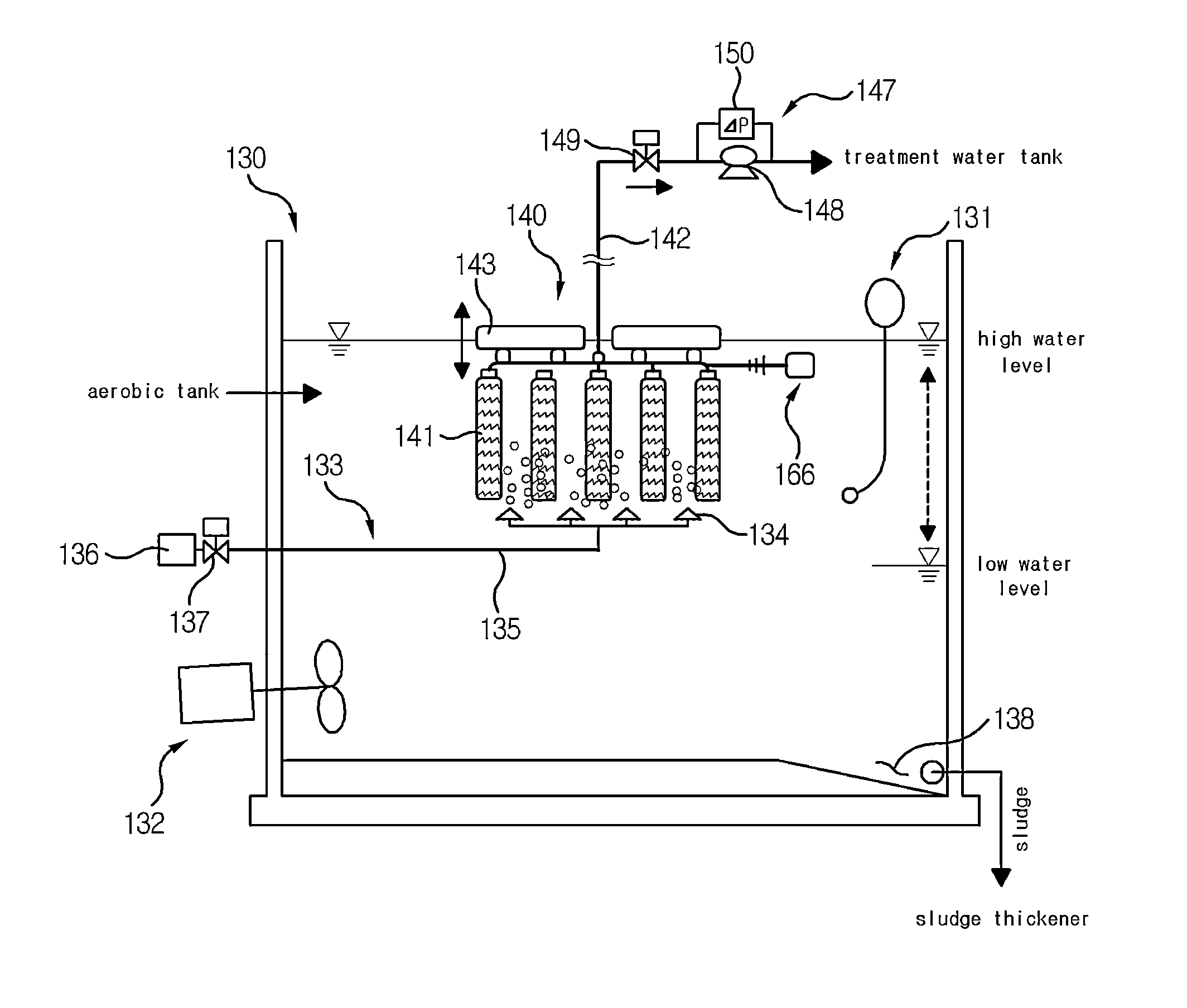
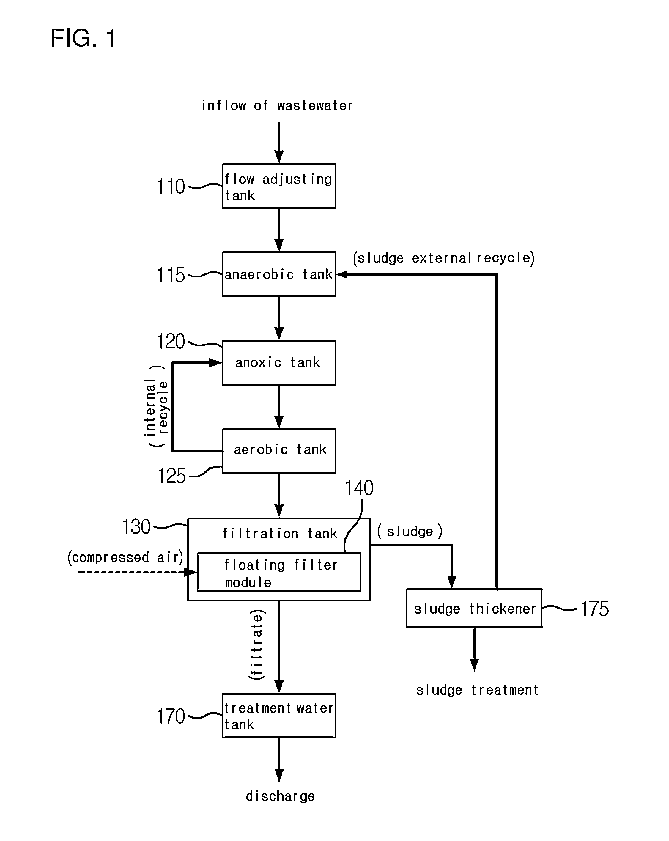
[0049]As shown in FIGS. 1 to 3, the present invention is an A2 / O (Anaerobic / Anoxic / Oxic) type of water treatment apparatus which includes three stages of bio-reactors comprising anaerobic tank 115, anoxic tank 120 and aerobic tank 125, and a plurality of treatment tanks arranged in the upper and downstream of the bio-reactors. Additional treatment tanks except for the three stages of bio-reactors are a flow rate control tank 110 arranged in the upper stream of the anaerobic tank 115, a filtration tank 130 arranged in the lower stream of the anoxic tank 120, a processing water tank 170 and a sludge thickener 175. A floating filter module 140 for separating and filtering wastewater is arranged in the filtration tank 130.

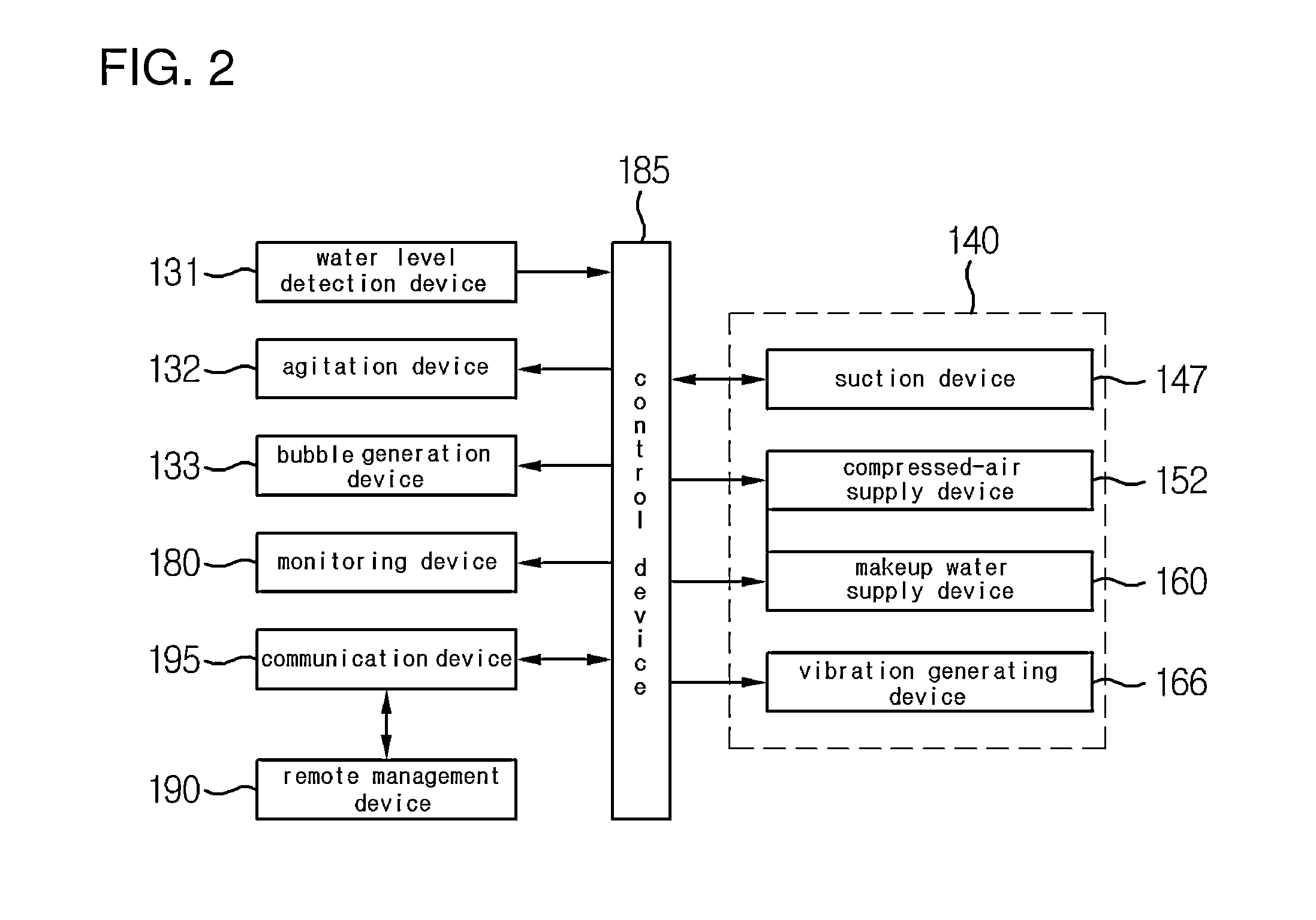
[0050]In addition, the water treatment apparatus according to the first embodiment of the present invention further includes a water level detection device 131 for detecting the water level of the filtration tank 130, a agitation device 132 for agitating the wastewater...

second embodiment

[0088]On the other hand, FIG. 8 is a flowsheet showing the wastewater treatment processes of a water treatment apparatus according to the present invention and FIG. 9 is a top view schematically showing the water treatment apparatus of FIG. 8.

[0089]The wastewater treatment apparatus according to the second embodiment of the present invention is medium and small sized wastewater treatment apparatus and includes a water flow adjusting tank 110; a denitrification and dephosphorization tank 210 for executing both functions of the anaerobic tank and anoxic tank according to the first embodiment of the present invention, and maintaining the concentration of dissolved oxygen below a predetermined level, for example 0.2 mg / L; an aerobic tank 215 in which the floating filter module 140 is installed; a dissolved oxygen reduction tank 225 for reducing the dissolved oxygen of the treatment solution returned to the denitrification and dephosphorization tank 210 to improve the denitrification and...

third embodiment

[0097]The water treatment apparatus according to the present invention is a sequencing wastewater treatment apparatus using a sequencing batch reactor (SBR) 310 for executing a series of processes that is inflowing—microorganism reacting—depositing—discharging, and includes a flow adjusting tank 110, a denitrification and dephosphorization tank 210, a sequencing batch reactor 310, a sludge transferring tank 325, a treatment water tank 170 and a sludge thickener 175. The denitrification and dephosphorization tank 210 is divided into an anaerobic region 212 and an anoxic region 213 by a partition wall so that the phosphorus removal reaction and the nitrogen removal reaction are not interfered each other. The anaerobic region 212 and the anoxic region 213 are connected through the pathway 214.

[0098]According to a conventional sequencing wastewater treatment method using a sequencing batch reactor 310 in major reaction process, the inflowing of wastewater—microorganism reacting—depositi...


PUM

PropertyMeasurementUnit
solids retention timeaaaaaaaaaa
lengthaaaaaaaaaa

Abstract

The present invention relates to a floating filter module installed in a water treatment apparatus, such as in a public water treatment plant, a village water supply facility, a public sewage treatment plant, a wastewater treatment plant, or a village sewage treatment plant, in order to remove contamination particles. The floating filter module according to the present invention comprises: a hollow-type sintered filter having a plurality of fine pores which is arranged in wastewater within a water treatment tank in order to separate and filter the contamination particles from the wastewater introduced into the water treatment tank; a floating body connected to the sintered filter, and which floats to the surface of the wastewater within the water treatment tank so as to position the sintered filter at the upper portion of the wastewater in the water treatment tank; a main pipe communicating with an inner space of the sintered filter; a suction device coupled to the main pipe in order to provide a suction force to the sintered filter through the main pipe, thereby suctioning the wastewater in the water treatment tank through the plurality of fine pores and into the sintered filter; and a compressed-air supply apparatus having a compressed-air supply tube communicating with the inner space of the sintered filter through the main tube and an air compressor coupled to the compressed-air supply tube in order to supply compressed air into the inner space of the sintered filter, thereby releasing from the sintered filter the contamination particles that clog the fine pores of the sintered filter.

Description

BACKGROUND OF THE INVENTION[0001]1. Field of the Invention[0002]The present invention relates to a floating filter module to remove micro-pollution particles, which is installed in a water treatment apparatus, such as in a public water treatment plant, a village water supply facility, a public sewage treatment plant, a wastewater treatment plant, or a village sewage treatment plant. More particularly, the present invention relates to a floating filter module for separating and filtering the upper water which is placed in the upper side of a wastewater tank and have relatively low concentration of suspension solids, and a water treatment apparatus and a method using the floating filter module.[0003]2. Description of the Related Art[0004]Environmental pollution like soil and air contaminations and global warming is becoming increasingly serious, and the amount of sewage, wastewater or dirty water (hereinafter referred to as the “wastewater”) has been greatly increased. As a result, tr...

Claims


Application Information

Patent Timeline
Patent Type & Authority Applications(United States)
IPC IPC(8): C02F1/00C02F3/30C02F3/12B01D35/05B01D35/16
CPCC02F1/001B01D35/05B01D35/16C02F3/1263C02F3/30C02F2307/00C02F1/004C02F1/74C02F2303/16B01D61/18B01D2315/06C02F3/308C02F2209/008C02F2209/40C02F3/006C02F2209/08C02F2209/44C02F3/302Y02A20/152Y02W10/10
Inventor WOO, KWANG JAEKIM, YEON GILKIM, WAN JUNG
Owner DAEWOONG ECOSYST & SOLUTION
Why Eureka
Try Eureka