
Performance of conductive copper paste using copper flake

a technology of conductive copper and flake, applied in the field of materials, can solve the problems of cracking and delamination, heat generated can decompose and vaporize polymers in the applied paste, and achieve the effect of improving the latitude of sintering

Inactive Publication Date: 2014-09-25
INTRINSIQ MATERIALS INC
View PDF8 Cites 14 Cited by
  • Summary
  • Abstract
  • Description
  • Claims
  • Application Information

AI Technical Summary

Benefits of technology

The present invention has been shown to improve the sintering of conductive pastes compared to traditional methods. This means that this technology allows for more flexibility in the way that the pastes can be heated and formed during a sintering process.

Problems solved by technology

The conventional method for forming copper traces is one example of this process, requiring multiple processing steps, with the use of toxic chemicals and the complications and cost of proper waste disposal.
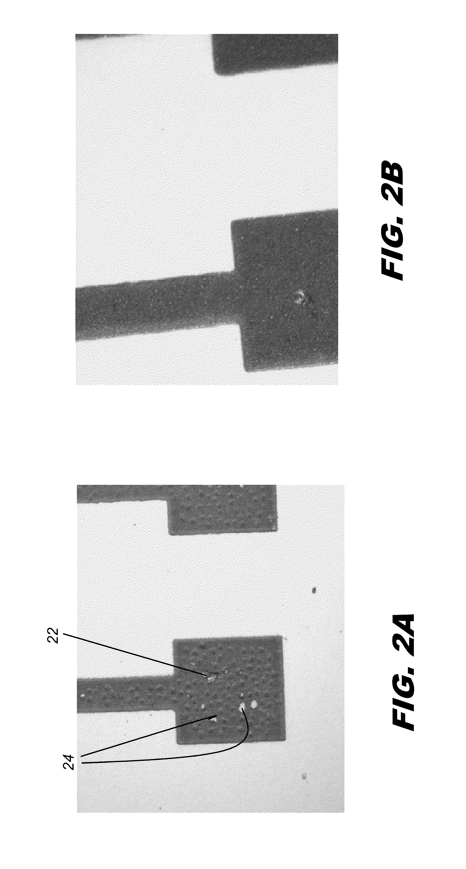
Because of the high localized energy levels required for sintering, cracking and delamination have been persistent problems for curing the applied materials.
However, the heat that is generated can decompose and vaporize polymers in the applied paste, including polymers used to coat the nanoparticles and polymers used as binder.
Venting of the resulting vapor can cause bubbling and cracking in the surface of the sintered trace, detrimental to good adhesion.
This dimensional instability can, in turn, introduce stresses in the sintered copper traces and cause cracks and delamination from the substrate and poor conductivity.(iii) Curing efficiency.
Conventional methods of curing conductive pastes include oven-curing, with use of high-energy illumination sources, such as Xenon bulbs, that can be relatively inefficient, causing wasted heat energy.
This is inefficient, since not all of the heat energy is used.
The needed levels of heat energy for this purpose can cause degradation of the substrate and effectively restricts the substrates that can be used, preventing the use of many types of plastics and other flexible and less costly substrates.(iv) Substrate options.
However, forming conductive traces on PET and other plastics remains challenging due to heat problems.
The desired levels of conductivity / resistivity can be difficult to achieve with current processes / ink formulations.
Higher resolution, using thinner conductive traces and allowing higher density of traces, is difficult to achieve with inefficient curing processes, due to factors such as surface distortion because of excess heat, for example.

Method used


Image

  • Performance of conductive copper paste using copper flake
  • Performance of conductive copper paste using copper flake

Examples


example 1

Comparative Paste A

[0042]Into a porcelain bowl was weighed 36.0 g of amorphous copper powder of mean diameter 4.5-7.0 micrometers (Cu CH UF 10 from Ecka Granules GmbH) and 9.0 g of polymer-coated copper nanoparticles of mean diameter 50 nm. To these powders was added 2.5 g of a resin consisting of 1.25 g of 40,00 C0 molecular weight polyvinlypyrrolidone (PVP), 1.0 g of ethylene glycol (EG), and 0.25 g of diacetone alcohol. The mixture was kneaded with a spatula until a thick paste was obtained. This paste was further mixed on a three roll mill until a uniform viscous paste was obtained.

Inventive Paste A

[0043]This paste was prepared as Comparative A above except that 36.0 g of copper flake with a mean diameter of 1.0-5.0 micrometers was used in place of the amorphous copper. One source of suitable copper flake is product CU 101 from Atlantic Equipment Engineers, Bergenfield, N.J.

[0044]The ratio of copper flake to nanoparticle copper is in the range from 2:1 to 5:1 by weight. The mean...

example 2

[0053]Inventive Paste B was prepared in the same way as Comparative A above, except that a flaked copper of mean particle size of 4.0-13 microns was used in place of the amorphous copper.

[0054]Inventive Paste C was similarly prepared to Inventive Paste B except that glycerol was added to the resin in place of a percentage of the other solvents such that the weight percentage of glycerol in the final paste was about 2%.

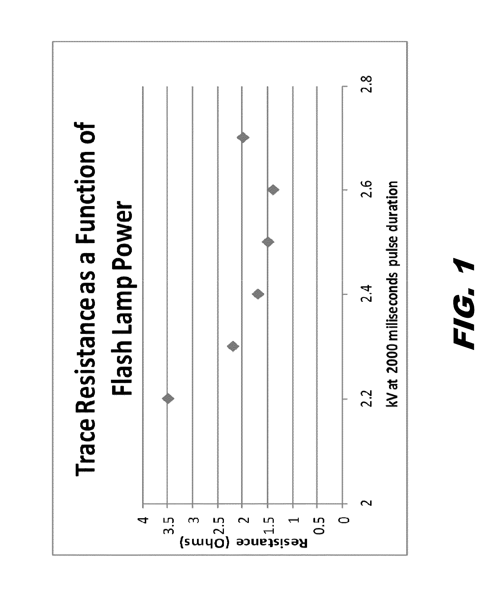
[0055]Comparative A and Inventive B and C were printed and sintered as above except that they were printed onto DuPont Melinex® 505 polyester film which is a temperature sensitive substrate. The sintering latitudes observed are shown in Table 1.

TABLE 1Sintering Latitudes for Example 2Sintering LatitudePasteMicro Copper Type(Joules)Comparative AAmorphous0Inventive BFlake378Inventive CFlake331

[0056]It can be seen from Inventive Pastes B and C that using copper flake in lieu of amorphous micron copper results in much larger sintering latitudes, making these materials more...

example 3

Comparative Paste B

[0057]Into a porcelain bowl was weighed 30.8 g of amorphous copper powder of mean diameter 4.5-7.0 micrometers (Cu CH UF 10 from Ecka Granules GmbH), 15.2 g of copper nanoparticles of mean diameter 40 nm, 5.8 g of a resin consisting of 2.9 g of 40,000 molecular weight polyvinlypyrrolidone (PVP), 2.3 g of ethylene glycol (EG), and 0.6 g of diacetone alcohol and 1.25 g of glass frit (DPS 149 from Asahi Glass Corp). The mixture was kneaded with a spatula until a thick paste was obtained. This paste was further mixed on a three roll mill until a uniform viscous paste was obtained.

Inventive Paste D

[0058]This paste was prepared as Comparative A above except that 30.8 g of copper flake with a mean diameter of 1.0-5.0 micrometers (CU 101 from Atlantic Equipment Engineers, Bergenfield, N.J.) was used in place of the amorphous copper.

Inventive Paste E

[0059]This paste was prepared as Comparative A above except that 30.8 g of copper flake of mean particle size of 4.0-13 micro...


PUM

PropertyMeasurementUnit
Lengthaaaaaaaaaa
Percent by massaaaaaaaaaa
Diameteraaaaaaaaaa

Abstract

A conductive paste for screen application has a mixture of copper flake having a mean diameter between 1.0-8.0 micrometers and copper nanoparticles having a mean diameter from 10 nm to 100 nm, wherein the ratio of the copper flake to the nanoparticles is between 2:1 and 5:1 by weight; and a resin comprising about half of a polymer having a molecular weight in excess of 10,000 and one or more solvents.

Description

CROSS-REFERENCE TO RELATED APPLICATIONS[0001]This application claims the benefit of U.S. Provisional Patent Application Ser. No. 61 / 803,839, filed on 21 Mar. 2013, entitled “Improving Performance of Conductive Copper Paste Using Copper Flake” in the names of Janet Heyen et al., the contents of which are incorporated fully herein by reference.FIELD OF THE INVENTION[0002]The invention relates generally to materials that are applied to a substrate and treated to form a conductive pattern thereon, and more particularly relates to a conductive copper paste formulation that uses a combination of metal flake and nanoparticle materials for forming conductive traces.BACKGROUND OF THE INVENTION[0003]Fabrication of mass-produced electronic items typically involves temperature- and atmosphere-sensitive processing. Conventional material deposition systems for electronic fabrication, including plasma-enhanced chemical vapor deposition (PECVD) and other vacuum deposition processes, rely on high te...

Claims


Application Information

Patent Timeline
IPC IPC(8): C09D5/24
CPCC09D5/24C08K9/10H01B1/22H01L23/49883H01L2924/0002H05K1/0306H05K1/0326H05K1/095H05K3/1216H05K2201/0145H05K2201/0154H05K2201/0158H05K2201/0224H05K2201/0245H05K2201/0266H05K2201/0272H05K2203/0514H01L2924/00
Inventor HEYEN, JANETCARMODY, MICHAEL
Owner INTRINSIQ MATERIALS INC
Learn More