
Dynamic thermal interface material

a thermal interface and material technology, applied in the field of thermal interface materials, can solve the problems of failure of semiconductor products, temperature exceeding the allowable limit of devices, and development of new functionalities, and achieve the effects of increasing thermal conductivity, increasing thermal conductivity, and increasing thermal conductivity

Inactive Publication Date: 2014-11-27
ANCHOR SCI
View PDF5 Cites 64 Cited by
  • Summary
  • Abstract
  • Description
  • Claims
  • Application Information

AI Technical Summary

Benefits of technology

The patent describes a method of creating a solid material made up of a mixture of carbon nanotubes and nanosized graphene particles. Curing this mixture can help maintain its properties and improve its performance for heat and electrical conduction. The curing process can also increase the density of the material and improve the interaction between the carbon nanotubes and nanosized graphene particles. This method can result in better performance of the solid material when exposed to electrical current. Additionally, using carbon nano-platelets with a specific size range can further enhance the heat conduction in the solid material.

Problems solved by technology

Typically natural heat dissipation from a powered device is insufficient, thus its temperature exceeds the allowable limit of the device.
Challenges in the ability to manage dissipated heat restrict the development of new functionalities and the durability of semiconductor devices [The International Technology Roadmap for Semiconductors. http: / / www.itrs.net / ].
Overheating is a major contributing factor to the failure of semiconductor products and more specifically to the failure of electronic parts.
Typically a 10° C. increase in operating temperature shortens useful product life by a factor of two.
By causing mechanical strains, thermal cycling also impairs the durability of the devices.
The performance of a TIM, however, is application dependent because of differences in surface roughness of the adjoining materials of the mating parts, and because of difference in the span of gaps to be bridged.
Cut-and-glue” attempts to reorient graphite to traverse the heat transport gap resulted in mechanically fragile products.
However, there is a tradeoff between the benefit of perfecting the surface finish and its cost.
These materials can be attacked by acids and alkalis and can be susceptible to hydrolysis.
However, diamond is prohibitively difficult to process, and costly.
Graphitized carbon foams have isotropic thermal conductivity, up to 150 W / m·K, they are mechanically fragile and have CTEs that are typical for graphite.
The main drawback of a high temperature synthetic route to carbon matrix composites, using a chemical vapor deposition (CVD) physical vapor deposition (PVD) method or high temperature consolidation, is the process temperature that the part is exposed to and the costly fabrication.
Carbon-carbon composites (graphitized pitch—carbon fiber or carbon nanotubes) have high thermal conductivity, but at 0.26 ppm / ° C. the CTE of carbon-carbon composites is too low to avoid thermal stresses on contact with common components of a thermal stack.

Method used


Image

  • Dynamic thermal interface material
  • Dynamic thermal interface material
  • Dynamic thermal interface material

Examples


example 1

Thermal Conductivity Changes as a Function of Temperature

[0169]A mixture was prepared of 1 (one) part by weight of short (2 μm on average) and thin (8 to 15 nm outer diameter) multiple walled carbon nanotubes with 2 (two) parts by weight of nanographite platelets with 0.3 μm on average lateral diameter, and at least ten times smaller average thickness.

[0170]The thermal conductivity change was measured as a function of temperature. Results for a first composition are shown in FIG. 3. Measurements were repeated for further D-TIM samples having a 1:2 by weight MWCNT: nG mix, and the results are shown in FIG. 4.

[0171]In one example, the following material composition was used: 95 to 98% elemental carbon by weight in that SMW 20×-L3 34% by weight, 66% graphite by weight such as for electron microscopy conductive paints, and 3% polymeric binders (polyacrylate). The resultant apparent density was 0.85 g / cm3 as a self-standing material after ambient cure. This was not measured after the the...

example 2

Methods of Preparing a D-TIM Nanocomposite

[0175]Material Composition:

[0176]A nanocomposite material was prepared to have the following composition: 3% polyacrylate binder by weight and 97% elemental carbon allotropes by weight, the carbons being: MWCNT 10±1 nm OD, 3 to 5 micron length at 34% by weight, and 66% graphite nanoplatelets: average lateral diameter 0.3 micron, average thickness below 30 nm. The material was assembled by a non-limiting mixing procedure that involves the following steps.

[0177]Mixing Procedure:

[0178]Step 1: Obtain a homogenous dispersion of a binder with graphite of appropriate dimensions in a solvent, e.g., isopropanol. This is dispersion A. Dispersion A can have a concentration of up to 25 weight percent of graphite in a solvent. Dispersion A can also contain up to 10% binder. The solvent can be a single chemical or a mix of liquid chemical species. The dispersion is a generic process resulting in a homogeneous mixture, such that 90% of particles pass throu...

example 3

Impact of Metal on Thermal Conductivity

[0195]A D-TIM was prepared with 66% nGP (obtained from SPI)+34% MWCNT (obtained from SWeNT)+10% Ag paint added. Relative thermal conductivities were measured in a temperature range of 18° C. to 82° C. The results shown in FIG. 6 indicate that no significant temperature dependence of thermal conductivity is found in the presence of Ag metal particles.


PUM

PropertyMeasurementUnit
operating temperatureaaaaaaaaaa
thermal conductivityaaaaaaaaaa
surface roughnessaaaaaaaaaa

Abstract

Aspects of the invention provide compositions that include carbon nanotubes dispersed within nanographite particles, and that have useful thermal properties. Certain compositions have high thermal conductivities (e.g., high thermal conductivities at ambient temperature). Certain compositions have a temperature dependent thermal conductivity that reversibly increases with temperature. Certain compositions are useful for heat transfer and can be used as thermal interface material, for example, in the context of computer and / or power generating devices.

Description

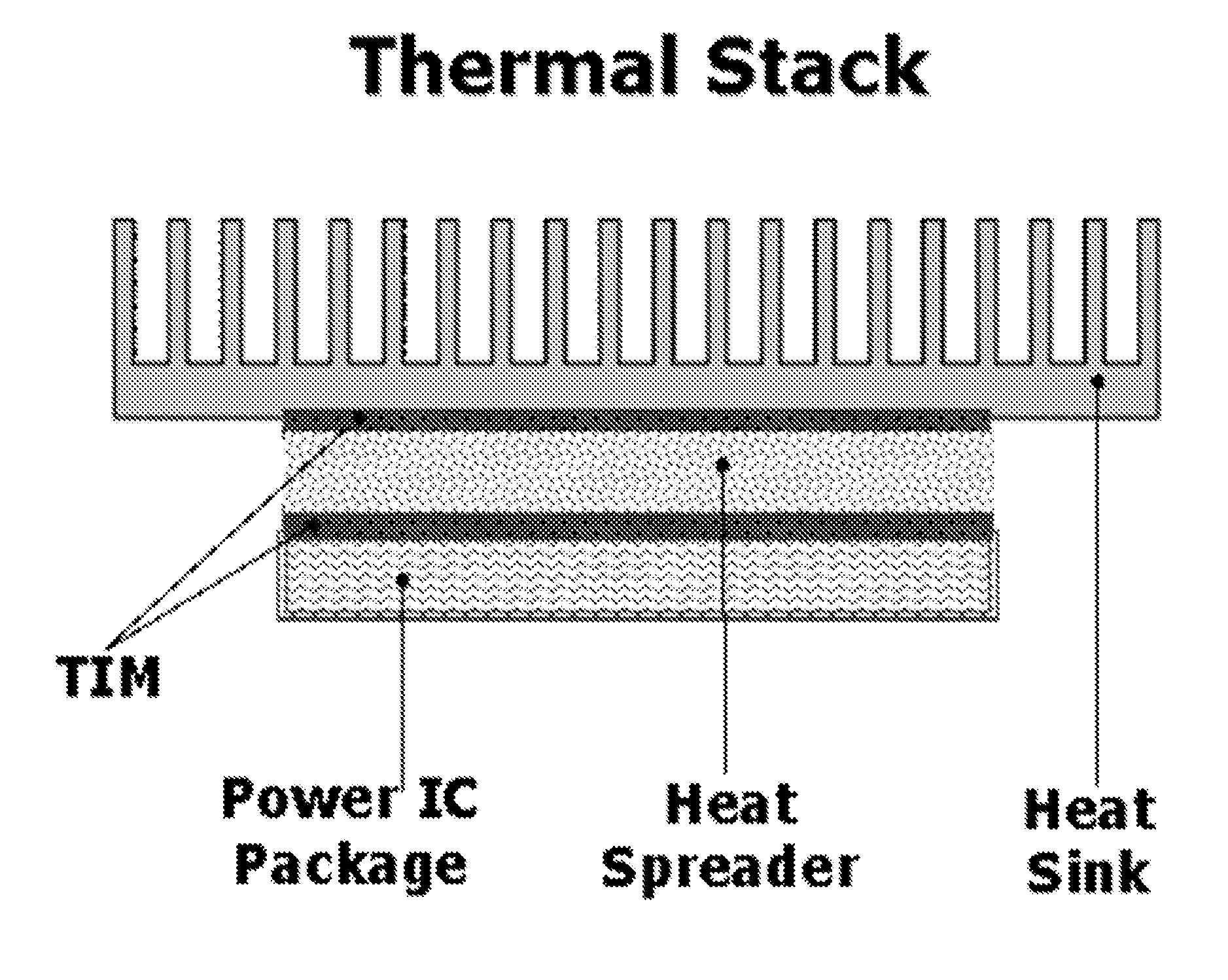
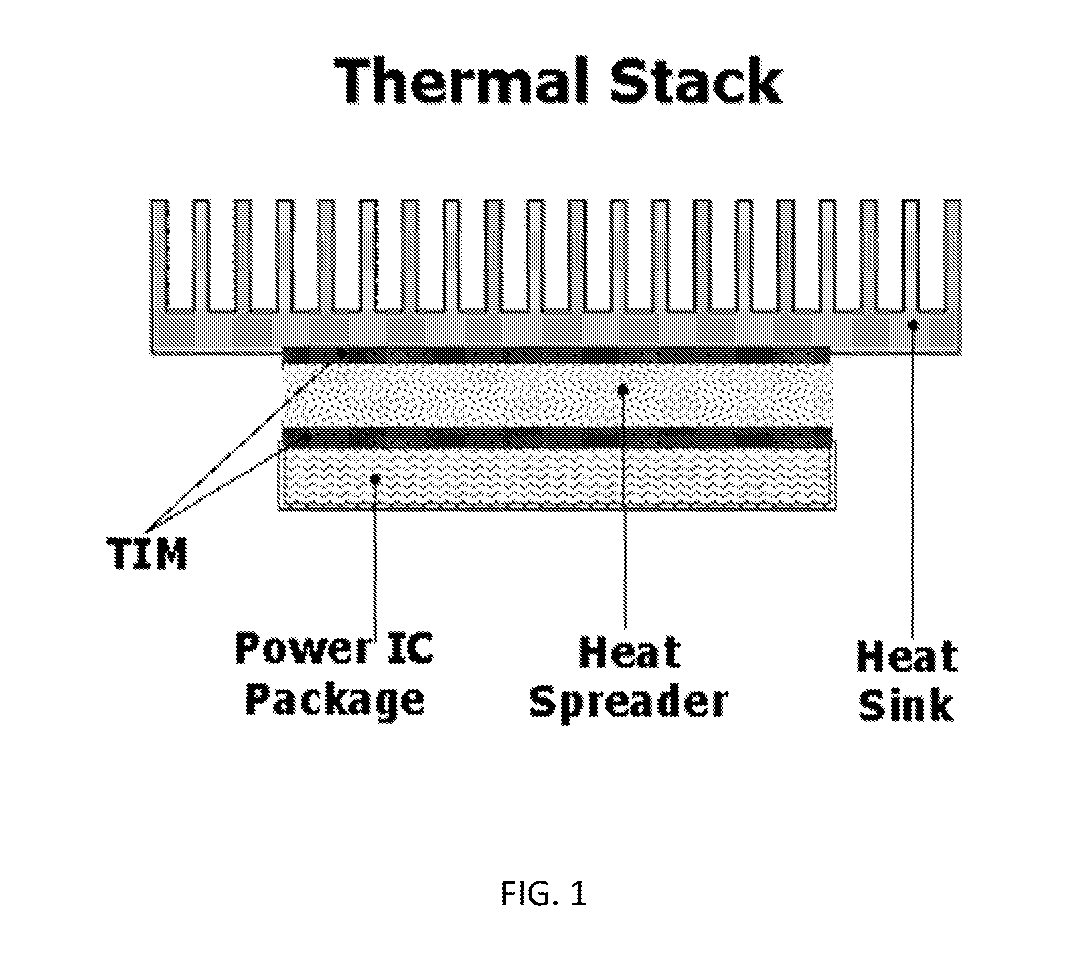
RELATED APPLICATIONS[0001]This application claims the benefit of U.S. Provisional Patent Application Ser. No. 61 / 514,715, filed Aug. 3, 2011, entitled “Dynamic Thermal Interface Material”, the contents of which are incorporated herein by reference.FIELD OF THE INVENTION[0002]Aspects of the invention relate to the field of thermal interface materials, including nanoparticulate materials.BACKGROUND OF THE INVENTION[0003]Typically natural heat dissipation from a powered device is insufficient, thus its temperature exceeds the allowable limit of the device. Thus, the ability to remove heat quickly from a powered or otherwise heated part is the key to the performance of the heated part (e.g., a processor, semiconductor, or other computer component). Heat transfer is typically managed by moving energy away from a power-dissipating part by conduction to a heat sink or an active cooling device, frequently through a thermal spreader, using thermal stacks and thermal interface materials (TIM)...

Claims


Application Information

Patent Timeline
Patent Type & Authority Applications(United States)
IPC IPC(8): F28F21/02C09K5/14H05K7/20
CPCF28F21/02C09K5/14H05K7/2039F28F23/00H01L23/373H01L23/433H01L2924/0002H01L2924/00
Inventor KIRKOR, EWA S.SCHRICKER, APRIL DAWNSINHA, SAION K.SCHEELINE, ALEXANDER
Owner ANCHOR SCI
Learn More