Iron oxide nanocomposite, magnetic resonance imaging t2 contrast medium comprising same, and method for manufacturing same

a technology of magnetic resonance imaging and nanocomposites, which is applied in the direction of diagnostics, sensors, diagnostic recording/measure, etc., can solve the problems of poor colloidal stability, difficult control of magnetic properties and relaxivity, and organ damage, and achieve significant t2 contrast effects

Inactive Publication Date: 2015-03-19
SEOUL NAT UNIV R&DB FOUND
View PDF1 Cites 3 Cited by
  • Summary
  • Abstract
  • Description
  • Claims
  • Application Information

AI Technical Summary

Benefits of technology

[0038]The present invention may provide nanocomposites comprising iron oxide nanoparticles having a size of 20 nm to 30 nm, and the iron oxide nanocomposite has a use of a biocompatible MRI T2 contrast agent.
[0039]In particular, since the r2 relaxivity of the MRI T2 contrast agent of the present invention is more than twice that of the conventional MRI T2 contrast agent comprising iron oxide nanoparticles having a size of more than 30 nm, it is possible to obtain significant T2 contrasting effects.

Problems solved by technology

However, these iron oxide nanoparticles, which are prepared by coprecipitation, are relatively polydisperse, and their magnetic property and relaxivity are difficult to control.
However, iron oxide nanoparticles in the SDR are ferrimagnetic, and their magnetic dipole interaction results in poor colloidal stability [D. Kim, N. Lee, M. Park, B. H. Kim, K. An, T. Hyeon, J. Am. Chem. Soc.
The severe agglomeration of ferrimagnetic iron oxide nanoparticles precludes their in vivo applications because their circulation time is very short, and they can sometimes cause organ damage because of capillary occlusion [P. Moroz, C. Metcalf, B. N. Gray, Biometals 2003, 16, 455].
However, to date, maximum r2 relaxivity could not be realized since the fraction of magnetic nanoparticles in the clusters is relatively small.
In addition, since nanoparticles are present as aggregates, as mentioned above, the retention time in bloodflow is too short.
Moreover, the aggregates may cause damage of organs.
Therefore, the conventional MRI contrast agent comprising iron oxide nanoparticles is only applicable to contrast cells.

Method used


Image

  • Iron oxide nanocomposite, magnetic resonance imaging t2 contrast medium comprising same, and method for manufacturing same
  • Iron oxide nanocomposite, magnetic resonance imaging t2 contrast medium comprising same, and method for manufacturing same
  • Iron oxide nanocomposite, magnetic resonance imaging t2 contrast medium comprising same, and method for manufacturing same

Examples


example 1

Preparation of Iron Oxide Nanocomposite

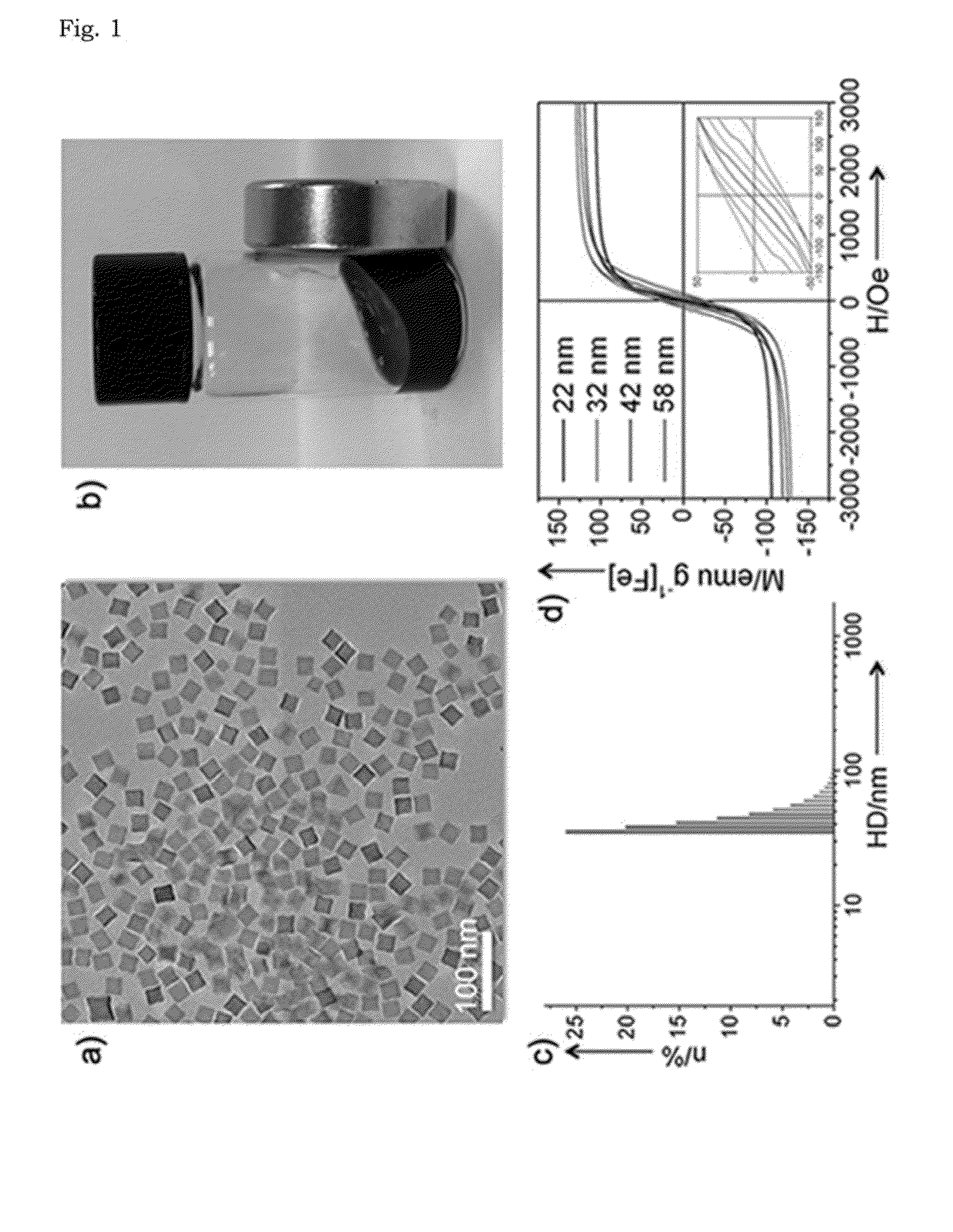
[0052]Iron (III) acetylacetonate (0.706 g, 2 mmol, Acros, 99%) was added to a mixture composed of oleic acid (1.27 g, 4 mmol, Aldrich, 90%), 4-biphenylcarboxylic acid (0.4 g, Acros 95%), and benzyl ether (10.40 g, 10 ml, Aldrich, 99%). The mixture solution was degassed at room temperature for 1 hour. The solution was then heated to 290° C. at the heating rate of 20° C. / min with vigorous magnetic stirring to prevent aggregation. The reaction mixture was maintained at this temperature for 30 minutes. After cooling the solution to room temperature, ethanol or acetone was added to the solution. The solution was then centrifuged at 1,700 rpm for 10 minutes to precipitate the particles. The separated precipitate (ferrimagnetic iron oxide nanoparticle (FION)) was dispersed in nonpolar solvent such as chloroform and n-hexane (10 ml).

[0053]The resulting nanoparticles were then encapsulated by PEG-phospholipid shell to endow them with biocompatibility an...

example 2

Characterization of Iron Oxide Nanocomposite

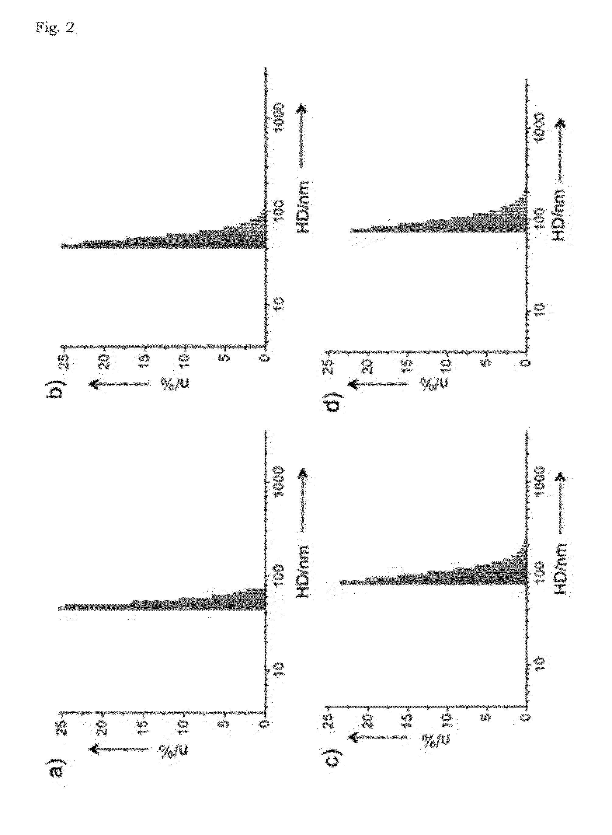
[0054]Transmission electron microscopy (TEM) images of the iron oxide nanocomposite obtained in Example 1 were taken on a JEOL JEM-2010 electron microscope at 200 kV. Samples were prepared by dropping small volume of particle dispersion onto a carbon-coated copper grid. The hydrodynamic diameters of nanoparticles were measured with a particle size analyzer (ELS-Z2, Otsuka). M-H curves were obtained by the vibrating sample magnetometer (VSM, Quantum Design PPMS). The iron concentrations of nanoparticles were measured with inductively coupled plasma atomic emission spectroscopy (ICP-AES) using ICPS-7500 spectrometer (Shimadzu).

[0055]The transmission electron microscopy (TEM) image shows that cube-shaped nanoparticles were obtained with an average size of 22±2.6 nm (FIG. 1a). Since the nanoparticles synthesized in the present Example are very hydrophobic, the iron oxide nanocomposites were transferred to aqueous media by encapsulation with po...

example 3

Measuring of MR Relaxivity of Ferrimagnetic Iron Oxide Nanoparticles (FIONs)

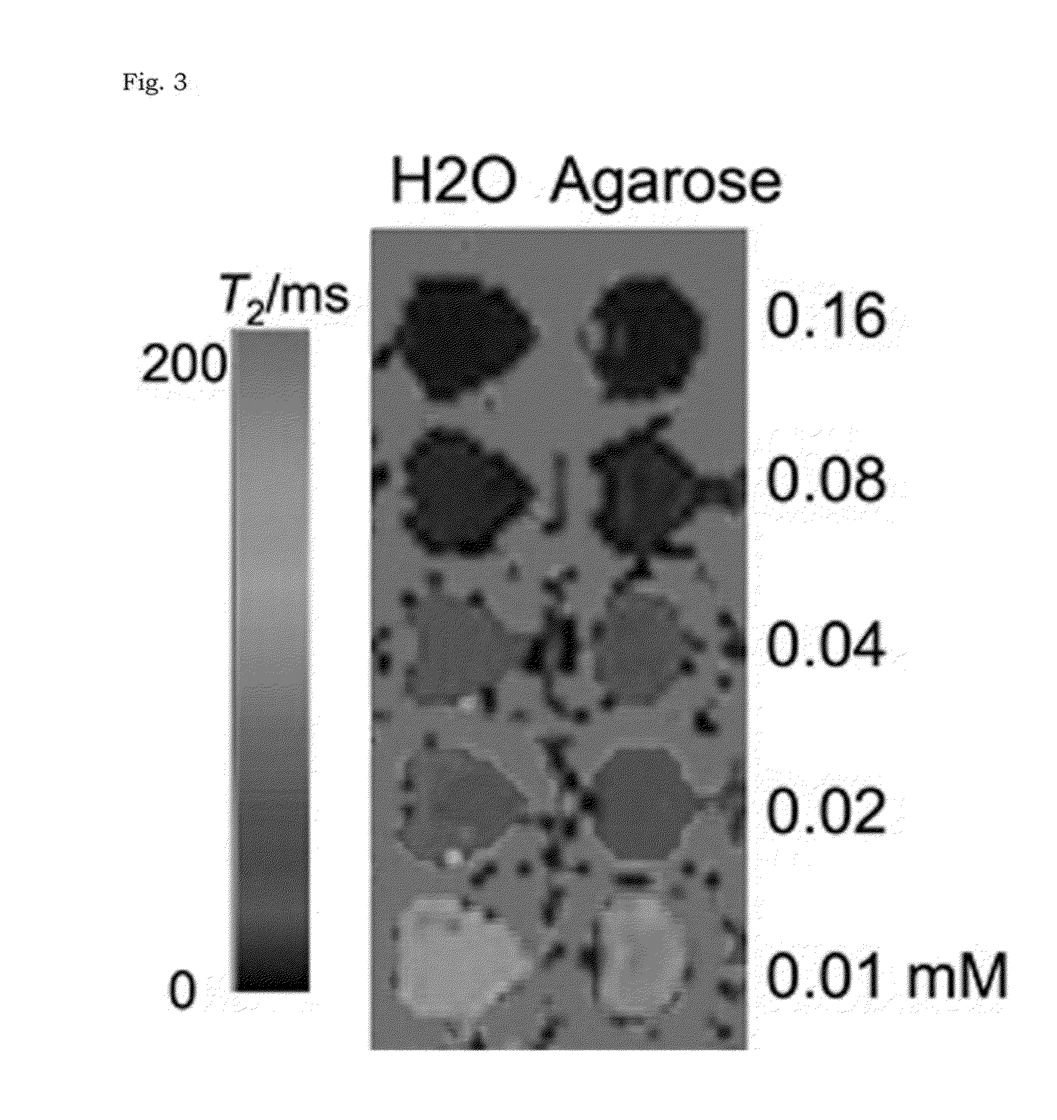
[0059]In order to measure MR relaxivity, ferrimagnetic iron oxide nanoparticles, obtained in Example 1, of 22, 28, 32, 42, and 49 nm in size were dispersed in 1% agarose solution (analytical grade agarose; Promega) to prevent sedimentation. T2 values of the nanoparticles were measured using the Carr-Purcell-Meiboom-Gill (CPMG) sequence with a head coil on a 3-T MR scanner (TrioTrim, Siemens): TR=5000 me, TE=16, 32, 48, 64, 20, 40, 60, 80, 50, 100, 150, 200 ms. Fast spin echo T2-weighted MR images of the phantom were acquired using the following parameters: flip angle=120, ETL=18, TR=6000 me, TE=90 ms, field of view FOV=119×170 mm2, matrix=448×640, slice thickness / gap=1.4 mm / 1.8 mm, NEX=1.

[0060]The r2 relaxivities of the iron oxide nanocomposites and larger ferrimagnetic iron oxide nanoparticles were measured using a 3-T clinical MR scanner. Given that the ferrimagnetic iron oxide nanoparticles larger than 30...


PUM

PropertyMeasurementUnit
temperatureaaaaaaaaaa
sizeaaaaaaaaaa
sizeaaaaaaaaaa

Abstract

The present invention relates to iron oxide nanocomposite, magnetic resonance imaging T2 contrast medium comprising same, and method for manufacturing same. More particularly, the present invention is directed to An MRI (magnetic resonance imaging) T2 contrast agent, comprising an iron oxide nanocomposite which includes an iron oxide nanoparticle, wherein said iron oxide nanoparticle is encapsulated with a surfactant and said surfactant is encapsulated with polyethylene glycol-phospholipid and method for preparing the same.

Description

TECHNICAL FIELD[0001]The present invention relates to iron oxide nanocomposite, magnetic resonance imaging T2 contrast agent comprising the same, and method for manufacturing the same. More particularly, the present invention is directed to an iron oxide nanocomposite comprising an iron oxide nanoparticle, wherein the iron oxide nanoparticle is encapsulated with a surfactant and the surfactant is encapsulated with polyethylene glycol-phospholipid, an MRI T2 contrast agent comprising the same, and method for preparing the same.BACKGROUND ART[0002]Magnetic nanoparticles have received enormous attention in various research areas because of their unique magnetic properties, facile surface modification, and biocompatibility. Magnetic nanoparticles have been used as contrast agents for magnetic resonance imaging (MRI) [Y.-w. Jun, J.-H. Lee, J. Cheon, Angew. Chem. 2008, 120, 5200; Angew. Chem. Int. Ed. 2008, 47, 5122; H. B. Na, I. C. Song, T. Hyeon, Adv. Mater. 2009, 21, 2133; J. Xie, G. L...

Claims


Application Information

Patent Timeline
Patent Type & Authority Applications(United States)
IPC IPC(8): A61K49/18
CPCA61K49/1818A61K49/1839A61K49/186A61K49/06A61K9/16A61K9/14
Inventor HYEON, TAEGHWANLEE, NOHYUNCHOI, SEUNG H.
Owner SEOUL NAT UNIV R&DB FOUND
Why Eureka
Try Eureka