Porous membrane apparatus, method, and applications

a membrane apparatus and membrane technology, applied in the field of microfluidic cell culture systems, can solve the problems of affecting the culture of tissues, metabolites produced in one tissue can travel, and none of these models recreate the three-dimensional villi structure that increases the absorption area

Active Publication Date: 2015-06-25
CORNELL UNIVERSITY
View PDF5 Cites 16 Cited by
  • Summary
  • Abstract
  • Description
  • Claims
  • Application Information

AI Technical Summary

Problems solved by technology

Moreover, metabolites produced in one tissue can travel to other organ compartments and affect the tissues cultured there.
A few microfluidic in vitro analogs of barrier tissues have been developed so far, but none of these models recreate the three dimensional villi structure that increases the absorptive area in the small intestine.
The existing models also do not combine other tissues with the developed models in one system.
However, sandwiching membranes between two existing tissue chambers is challenging.
It is not always possible to assemble such systems so that they are leak-free.
Because sheets of membranes are difficult to integrate with microfluidic systems, multi-organ cell culture devices are limited in regards to the barrier tissues they contain.
This process is not straightforward if the desired chamber depth is less than the thickness of the silicon substrate (˜500 μm), which is typically the case in “body-on-a-chip” devices.
In addition, both commercially available membranes and microfabricated membranes are typically flat and do not recreate the three-dimensional aspects of tissues such as the macro villi of the gastrointestinal tract epithelium.
Conventional models of the gastrointestinal tract such as Caco-2 monolayers do not provide three-dimensional surfaces that take the geometric character of the tissue into account.
Other prefabricated membranes also do not mimic the appropriate three-dimensional structure of tissue, (that means they are not three-dimensional) because they either lack the required rigidity to control a 3-D three-dimensional and / or lack sufficient porosity.
Accordingly, access to the underside of the cell culture is not possible with these methods.

Method used


Image

  • Porous membrane apparatus, method, and applications
  • Porous membrane apparatus, method, and applications
  • Porous membrane apparatus, method, and applications

Examples


example 1

Fabrication of Microfluidic Chambers with Flat Porous Membranes

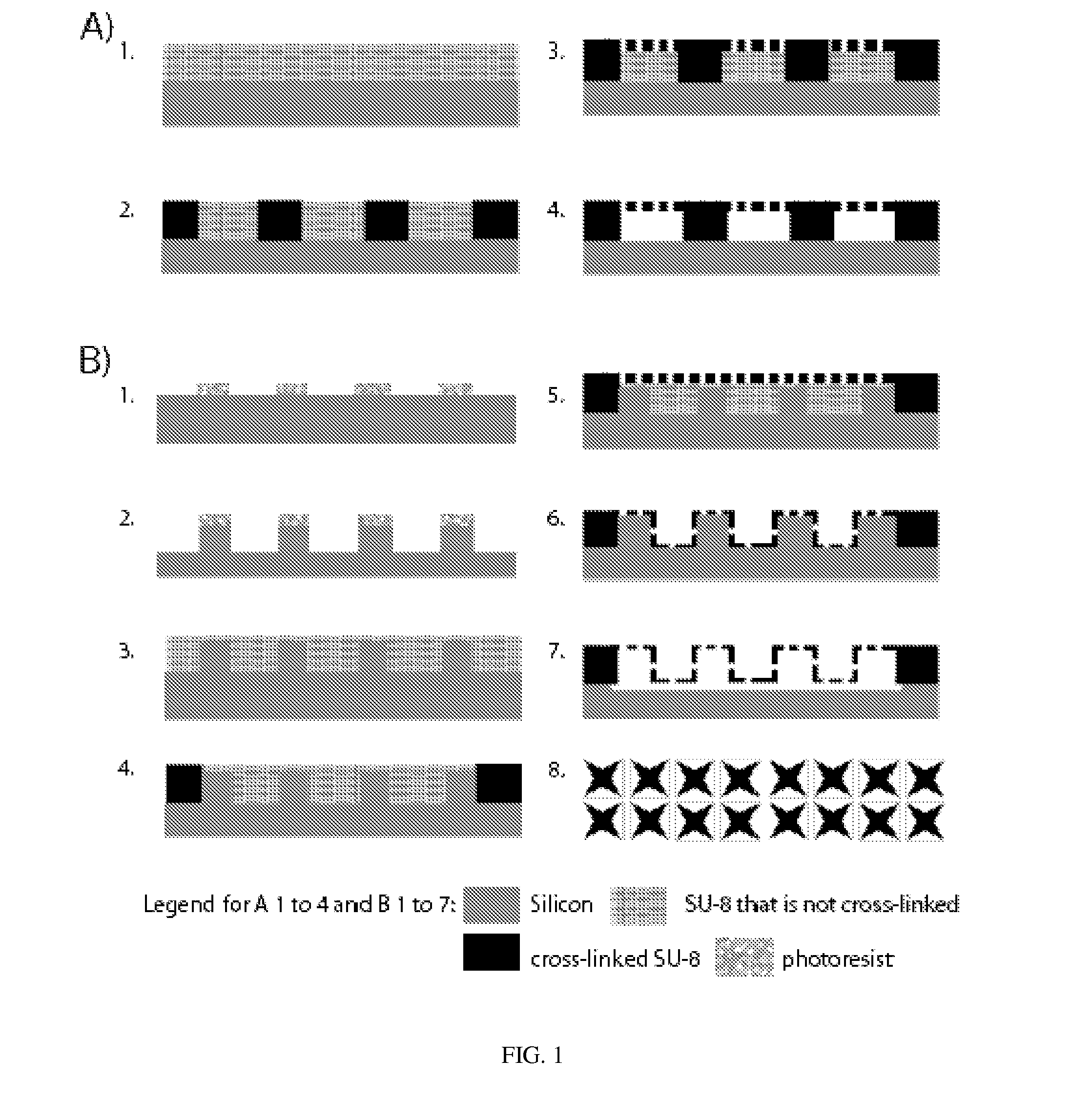
[0063]According to one embodiment, a membrane fabrication technique consists of a two-step exposure of a 50 μm thick SU-8 layer spun on a silicon wafer. The first exposure defines the walls of the microfluidic chamber as well as membrane support posts inside the chamber. The second exposure is a partial exposure that cross-links the top 0.5-4 μm of the remaining SU-8. An embodiment is represented in FIG. 1A.

[0064]Other photosensitive materials may be used, including but not limited to KMPR, acrylate-based Intervia BPN, and many other materials.

[0065]According to one aspect, a 50 μm thick layer of SU-8 2050 (Microchem, Newton, Mass.) was spun-coated onto a silicon wafer at 2800 rpm for 60 sec and soft baked at 65° C. for 2 min, then 95° C. for 5 min before patterning using the EV620. Patterning of the SU-8 via the contact aligner was separated into two exposure steps: a long exposure (720 mJ / cm2) that defines the microflu...

example 2

Fabrication of Microfluidic Chambers with Porous Membranes for Three-Dimensional Caco-2 Cell Culture

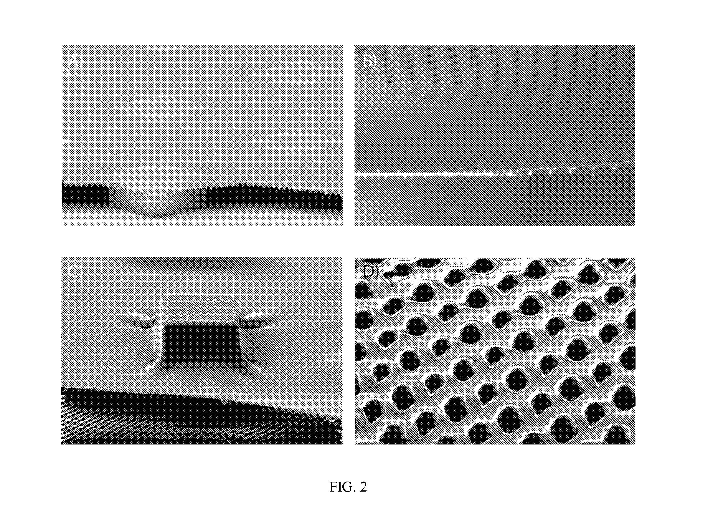
[0066]According to one embodiment, porous membranes were formed over silicon pillars with square cross sections of different sizes (25, 50, or 100 μm wide) and densities (25, 50, 100, or 200 μm between pillars) using conventional photolithography techniques. An embodiment is represented in FIG. 1B. Briefly, silicon wafers were primed with P-20 primer (Shin EtsuMicroSi, Tokyo, Japan) at 3000 rpm for 30 sec and then spin coated with a 2-μm-thick layer of SC 1827 photoresist (3000 rpm for 30 sec) (Shipley, Marlborough, Mass.) baked for 1 min at 115° C. Pillar arrays were then patterned into the photoresist at 96 mJ / cm2 with an EV620 contact aligner (Electronic Visions Inc., Phoenix, Ariz.) and developed in AZ 300 MIF (AZ Electronic Materials, Somerville, N.J.) for 1-2 min. Pillars 100 um tall were etched into the silicon via Bosch fluorine etch (Unaxis 770 Si Etcher, Plasma-Therm Inc., S...

example 3

Fabrication of Microfluidic Chambers with Three-Dimensional Porous Membranes and Increased Chamber Depth

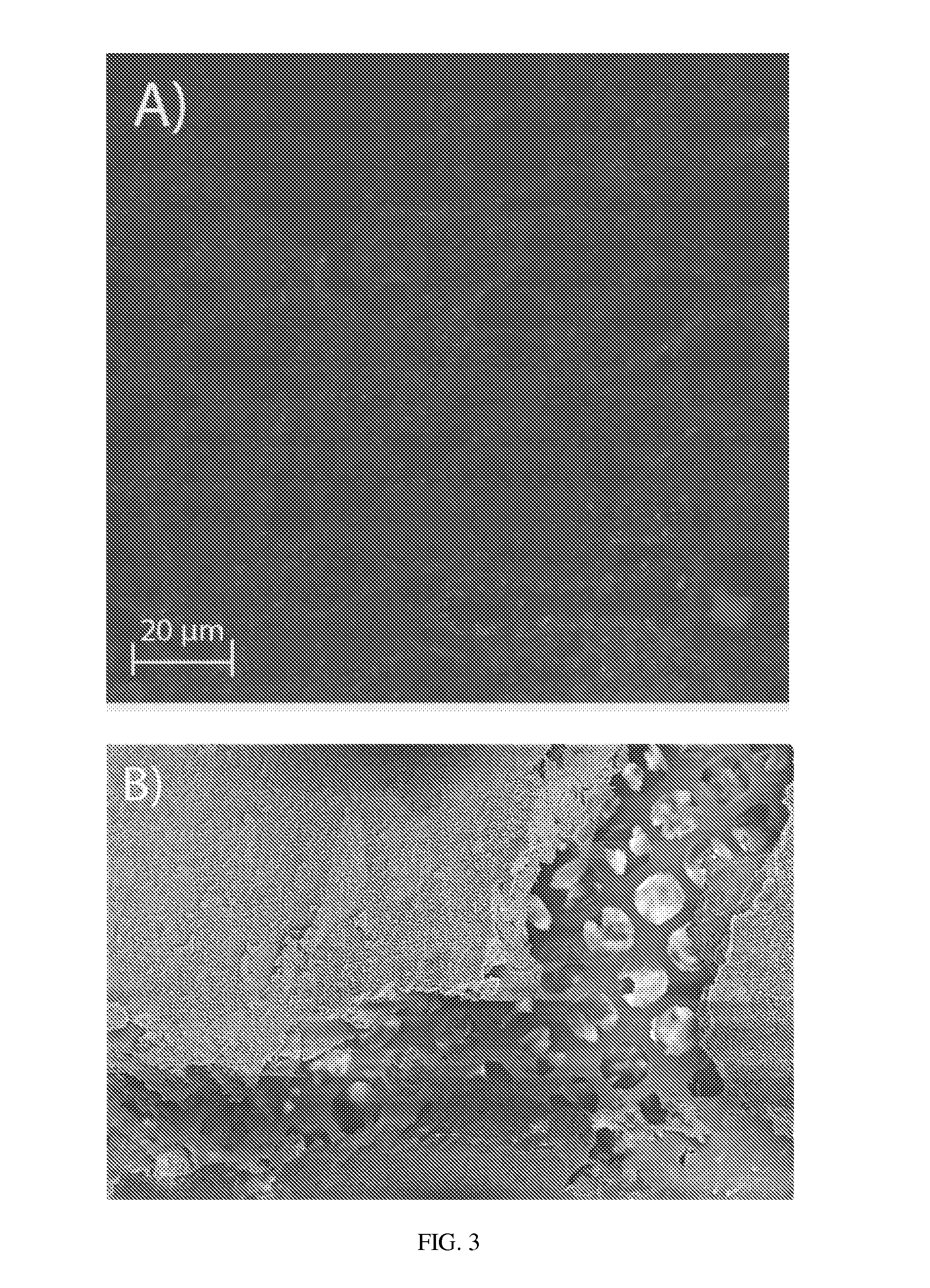
[0068]According to another embodiment, silicon pillars were created using an alternative method. Pursuant to this method a silicon nitride film was grown (500 nm) at 1100° C. on silicon wafers (Silicon Quest, Santa Clara, Calif.) using the process gases SiH2Cl2, NH3, and N2O in a furnace tube. The wafers were then coated with photoresist S1813 (Shipley, Marlborough, Mass.) at a spin speed of 3000 rpm and the area surrounding the pillars was exposed for 4 s using an AB-M HTG 3HR contact aligner (AB-M, San Jose, Calif.). They were then developed for 2 min and the exposed silicon nitride was removed using a reactive ion etcher (Oxford 80, Oxford Instruments, Tubney Woods, Abingdon, Oxfordshire, OX13 5QX, UK) with 50 sccm CHF3 and 2 sccm O2 at 50 mTorr and 200 W. The exposed substrate was etched to a depth of 20 μm using a 50% KOH solution at 80° C. The remaining silicon nitride was r...


PUM

PropertyMeasurementUnit
thicknessaaaaaaaaaa
chamber depthsaaaaaaaaaa
distanceaaaaaaaaaa

Abstract

Microporous membranes formed in a microfluidic device, and methods of manufacture. A method comprises the steps of etching a plurality of pillars in a microfluidic chamber, applying a first polymer material layer, applying a photoresist layer, exposing the photoresist layer to radiation to cross-link it to the microfluidic chamber, masking the photoresist layer with a porous mask, exposing the top layer of the masked photoresist layer to radiation to form a porous membrane layer of cross-linked photoresist material, removing the non-exposed photoresist material from under the porous membrane layer, drying the porous membrane layer, and removing the first polymer material from under the porous membrane layer.

Description

CROSS-REFERENCE TO RELATED APPLICATIONS[0001]This application claims priority to U.S. Provisional Patent Application Ser. No. 61 / 668,224, filed on Jul. 5, 2012 and entitled “Three Dimensional Porous Membrane Apparatus, Method, and Applications,” the entire disclosure of which is incorporated herein by reference.GOVERNMENT FUNDING[0002]This invention was made with Government support under Grant Number CERL-W9132T awarded by the Army Corps of Engineers and CBET-1106153 awarded by the NSF. The United States Government has certain rights in the invention.BACKGROUND OF THE INVENTION[0003]1. Field of the Invention[0004]The present invention relates to microfluidic cell culture systems and, more specifically, to microfluidic cell culture systems comprising microporous, polymeric, flat or three-dimensional membranes that can mimic barrier tissue. These membranes can be incorporated into, and fabricated simultaneously with, a microfluidic chamber. Accordingly, the fabrication allows for leak...

Claims


Application Information

Patent Timeline
Patent Type & Authority Applications(United States)
IPC IPC(8): B01L3/00G03F7/20
CPCB01L3/502707G03F7/2022B01L2200/12B01L2200/10B01L2200/0647C12M23/16C12M25/02C12M25/14
Inventor ESCH, MANDY B.
Owner CORNELL UNIVERSITY
Why Eureka
Try Eureka