Entry sheet for cutting fiber reinforced composite material or metal, and cutting method for cutting fiber reinforced material or metal

a technology of fiber reinforced composite materials and cutting methods, which is applied in the direction of turning machine accessories, metal-working apparatus, synthetic resin layered products, etc., can solve the problems of reducing the strength of conventional aluminum alloys, short drilling life, and short drilling life, etc., to reduce the wear of cutting tools, improve productivity, and reduce the load on cutting tools

Inactive Publication Date: 2016-02-18
MITSUBISHI GAS CHEM CO INC
View PDF2 Cites 22 Cited by
  • Summary
  • Abstract
  • Description
  • Claims
  • Application Information

AI Technical Summary

Benefits of technology

[0032]In cutting of a fiber reinforced composite material (for example, the CFRP), the load to a cutting tool (for example, a drill) can be reduced to suppress the wear of the cutting tool (for example, a drill) and, in the case of drilling, to obtain high-quality processed holes having a uniform inner diameter of the processed holes by using an entry sheet of the present invention. As a result thereof, cutting (for example, drilling) that is high-quality and is excellent in productivity becomes possible.
[0033]Moreover, in cutting of a metal, by using the entry sheet of the present invention, the load to the cutting tool (for example, a drill) can be reduced to suppress the wear of the cutting tool (for example, a drill) and to make the lifetime of cutting (for example, drilling) long. As a result thereof, cutting (for example, drilling) that is more excellent in productivity than that of the conventional technologies becomes possible.
[0034]Furthermore, in cutting of a fiber reinforced composite material and / or a metal, heat accumulation around a cutting portion generated during cutting can effectively be reduced according to the cutting method for cutting a metal of the present invention, and therefore high-quality processing in which the amount of burrs produced around the cutting portion is extremely smaller as compared with the conventional processing can be performed. Drilling that is more excellent in productivity and product quality than those in the conventional technologies is made possible particularly in drilling.

Problems solved by technology

Moreover, since the CFRP are difficult-to-cut materials, drilling lifetime is very short in the case where drilling of the CFRP is performed.
However, in the method described in Patent Document 6, the CFRP are the stiffening plate and are not the object of cutting, and the technology on a stiffening plate for processing the CFRP does not exist.
Furthermore, when the speedup of air crafts advances in the future, the strength of the conventional aluminum alloys is lowered due to aerodynamic heating.
For example, since the titanium alloy materials are difficult-to-cut materials, drilling lifetime is very short.

Method used


Image

  • Entry sheet for cutting fiber reinforced composite material or metal, and cutting method for cutting fiber reinforced material or metal
  • Entry sheet for cutting fiber reinforced composite material or metal, and cutting method for cutting fiber reinforced material or metal
  • Entry sheet for cutting fiber reinforced composite material or metal, and cutting method for cutting fiber reinforced material or metal

Examples


examples

[0170]Hereinafter, the present invention will be explained specifically showing Examples and Comparative Examples. In addition, the following Examples merely show an example of the embodiments in the present invention, and the present invention is not limited to these Examples.

[0171]Specifications of the resins components, etc. used for production of entry sheets of Examples 1-1 to 1-9 and specifications of bored materials and apparatuses used for evaluation in Examples 1-1 to 1-9 and Comparative Examples 1-1 to 1-5 are shown in Table 1-1.

TABLE 1-1Product name / CategorySignNamemodel numberManufacturerNotesResin—Polyethylene glycol / dimethylPaogen PP-15DKS Co., Ltd.Mw = 100,000componentsterephthalate polycondensate—Polyethylene oxideAltop MG150Meisei Chemical Works,Mw = 150,000Ltd.—Polyethylene glycolPEG4000SSanyo ChemicalMw = 4,000Industries, Ltd.—Polyoxyethylene monostearateNONION S-40NOF CORPORATIONMw = 3,500Solid lubricant—GraphiteX-100Ito Graphite Co., Ltd.Scaly, average particle ...

examples 1-1 to 1-9

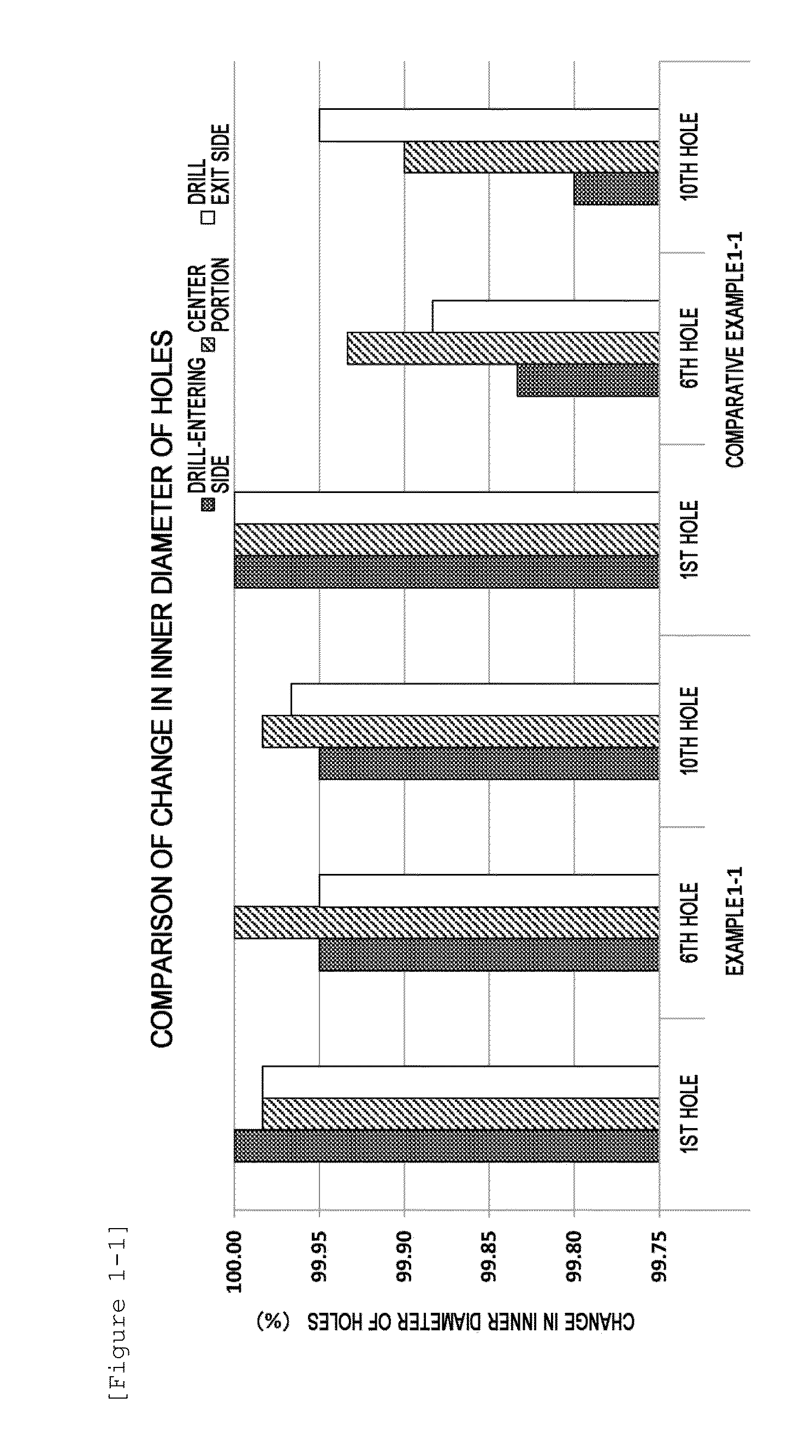
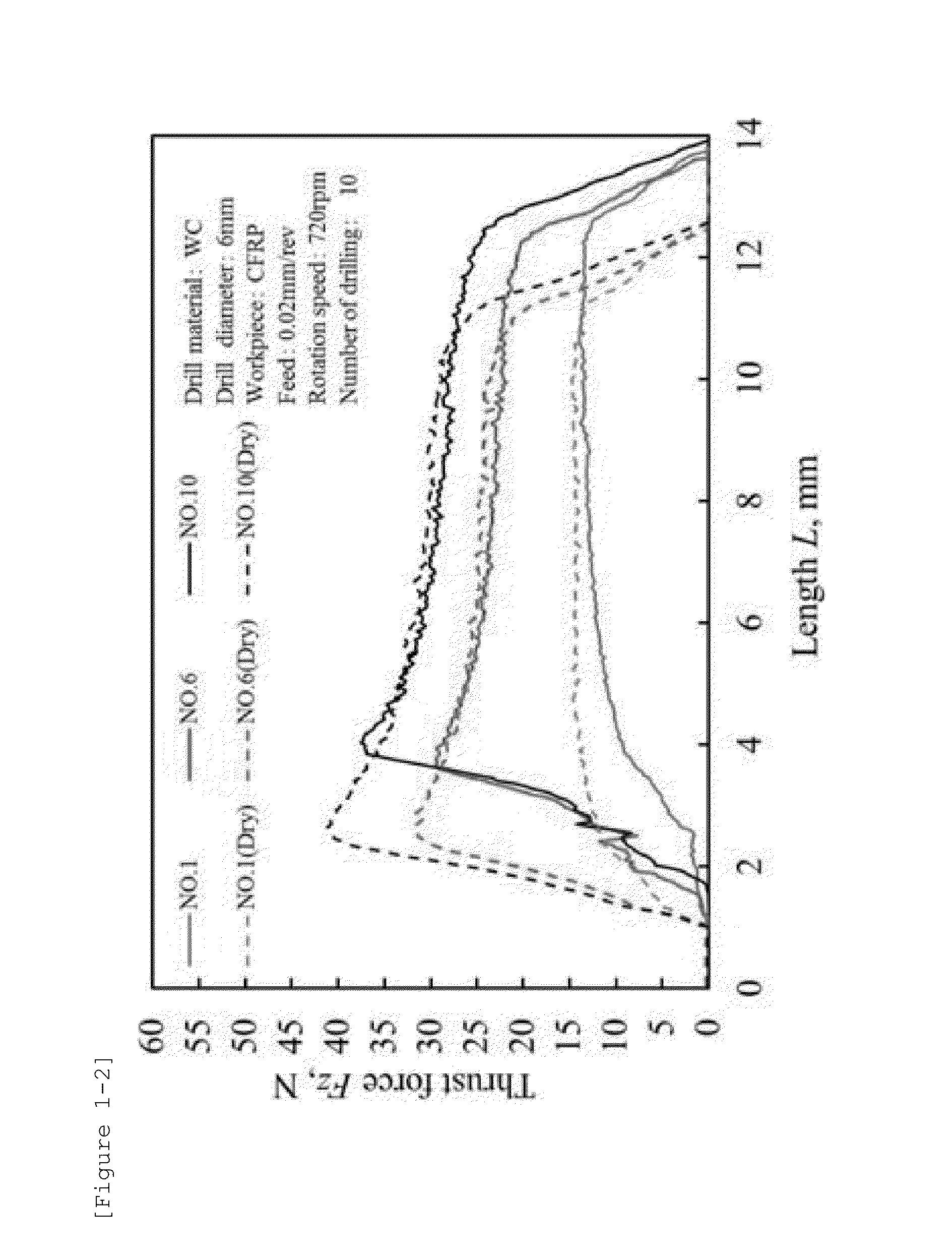
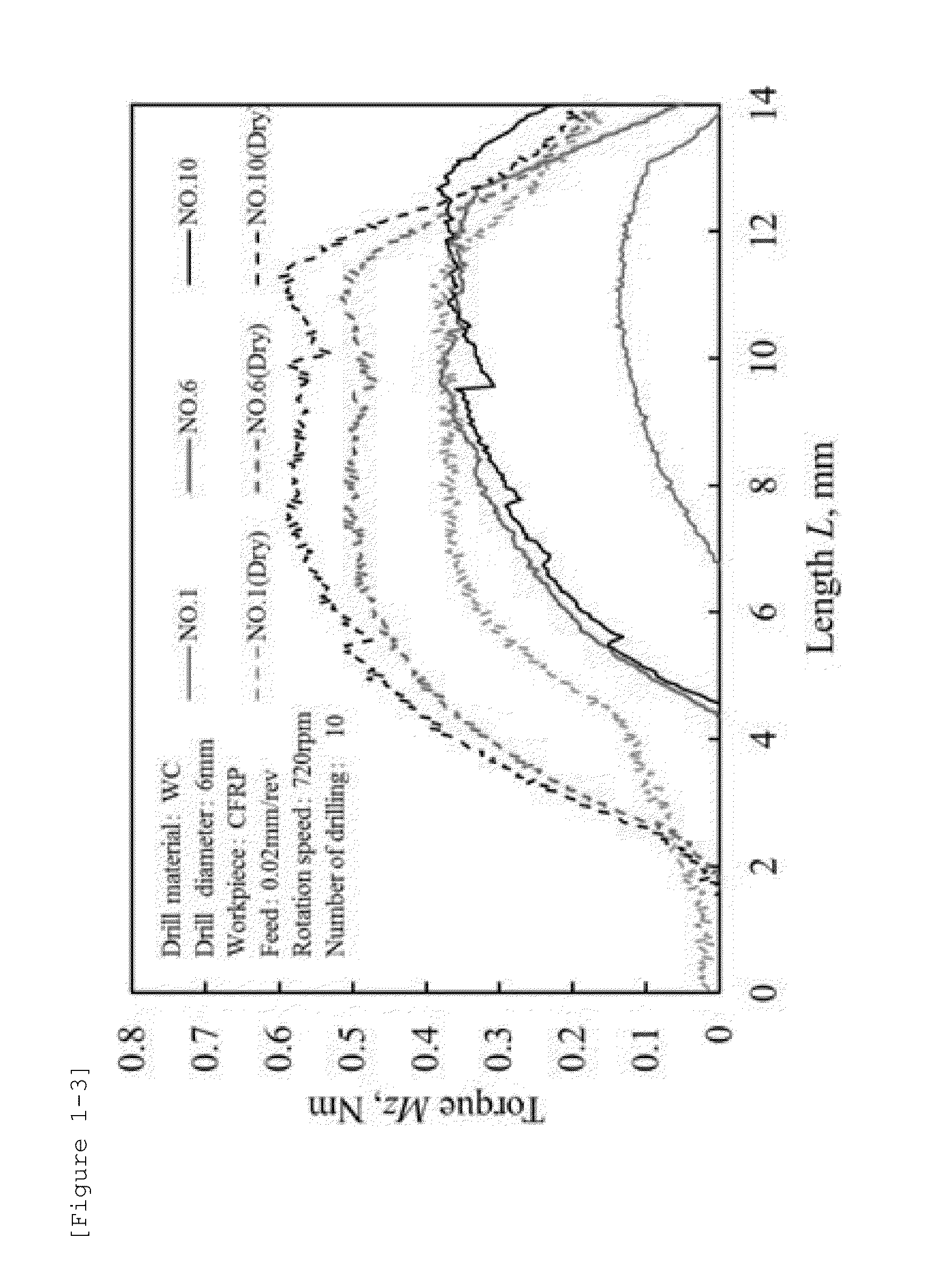
[0177]Each sheet prepared in the manner as described above was fixed on a cutting tool (cemented carbide drill)-entering face of the workpiece with a jig. With respect to Examples 1-2 to 1-9, the entry sheet was arranged so that the aluminum foil of the entry sheet contacted the cutting face of the workpiece. Boring was performed under the cutting condition with the cemented carbide drill where the number of revolutions was 5,000 rpm and the feed rate was 500 mm / min and also under the condition, as other conditions, as shown in Table 1-2. With respect to Example 1-1, the thrust force, the cutting torque, the wear loss of the drill, the inner diameter of holes, the change in inner diameter of holes were evaluated. The evaluation results are shown in Table 1-3. With respect to Examples 1-2 to 1-9, the inner wall roughness of holes and the wear loss of the drill were evaluated. The evaluation results are shown in Table 1-4.

example 2-1 to 2-9

[0193]Each entry sheet prepared in the manner as described above was fixed on the cutting tool (cemented carbide drill)-entering face of the workpiece with a jig, and boring was performed under the conditions shown in Table 2-2. In addition, with respect to Examples 2-2 to 2-9, the entry sheet was arranged so that the aluminum foil of the entry sheet contacted the cutting face of the workpiece. The wear loss of the drill after boring was evaluated. The evaluation results are shown in Table 2-3. Moreover, with respect to Examples 2-5 to 2-7, cutting (air-cooled cutting) was performed while supplying the air compressed with a compressor and having a temperature of 25° C. from a position 300 mm apart from the cutting portion to the cutting portion at 155 L / min using a nozzle having a cross-sectional area at the nozzle tip of 31.7 mm2. In addition, a titanium alloy plate and a carbon fiber reinforced plastic (CFRP) as the objects of cutting were overlaid so as to contact each other, and...


PUM

PropertyMeasurementUnit
thicknessaaaaaaaaaa
thicknessaaaaaaaaaa
temperatureaaaaaaaaaa

Abstract

An entry sheet of the present invention is used in cutting a fiber reinforced composite material and/or a metal. Moreover, in a cutting method of the present invention, cutting of a fiber reinforced composite material and/or a metal is performed using the entry sheet.

Description

TECHNICAL FIELD[0001]The present invention relates to an entry sheet for cutting a fiber reinforced composite material or a metal, and to a cutting method for cutting a fiber reinforced composite material or a metal.BACKGROUND ART[0002]Fiber reinforced composite materials represented by fiber reinforced plastics (FRP), and, among others, carbon fiber reinforced plastics (CFRP) have larger tensile strength and tensile elastic force and a smaller density as compared with glass fiber reinforced plastics (GFRP), aramid fiber reinforced plastics (AFRP), and stainless steel materials (SUS), and therefore there is a tendency that these plastics have frequently been used for outside plates or the like of air crafts and vehicles in recent years. The CFRP here denote plastics produced by laminating one or two or more prepregs obtained by impregnating a matrix resin into carbon fiber and then conducting heat molding or heat and pressure molding. Members formed from the CFRP are fixed to a stru...

Claims


Application Information

Patent Timeline
Patent Type & Authority Applications(United States)
IPC IPC(8): B23B35/00B32B7/12B32B15/08C08G63/183C08K3/04C08K3/10
CPCB23B35/00C08G63/183C08K3/04C08K3/10B32B15/08B23B2222/04C08K2003/045B23B2226/275B23B2250/12B23B2222/28B23B2222/88B32B7/12B26F1/16B23B2215/04
Inventor UMEHARA, NORITSUGUTOKOROYAMA, TAKAYUKIMATSUYAMA, YOUSUKEHASAKI, TAKUYA
Owner MITSUBISHI GAS CHEM CO INC
Why Eureka
Try Eureka