
Method of cladding, additive manufacturing and fusion welding of superalloys and materialf or the same

applied in the field of fusion welding and filler materials, can solve the problems of low ductility of turbine blades manufactured of nickel and cobalt based precipitation hardening and directionally solidified superalloys, poor mechanical properties of brazed joints that do not allow extensive dimensional restoration of turbine blades and other engine components, and low ductility of turbine blades manufactured of nickel and cobalt based precipitation hardening and productivity of welding operations a superalloys and superalloys superalloy fusion welding and superalloy fusion welding superalloy fusion welding and additive manufacturing and a technology of superalloys and additive manufacturing and fusion welding and superalloys and additive manufacturing and fusion welding and a technology, applied in the field of a fusion welding and a technology, which is applied in the field of a technology applied in the field fusion welding and fusion welding and fusion welding technology

Inactive Publication Date: 2016-06-16
LIBURDI ENG
View PDF15 Cites 52 Cited by
  • Summary
  • Abstract
  • Description
  • Claims
  • Application Information

AI Technical Summary

Benefits of technology

The patent describes a method of cladding and fusion welding that involves applying a composite filler powder containing brazing and high temperature welding powders to a base material. The filler powder is heated to melt the brazing powder and the high temperature welding powder, creating a continuous interconnected framework of dendrites and a braze based matrix. The weld is then heated to a temperature that allows for self-healing of cracks. The method can be used to repair and dimensionally restore structural components made of polycrystalline, directionally solidified, single crystal, and composite materials. The resulting welds have superior mechanical properties and oxidation resistance.

Problems solved by technology

However, accommodation of solidification and residual stresses often results in cracking of difficult to weld Inconel 713, Inconel 738, Rene 77, Rene 80, CMSX-4, Rene N4 and other superalloys with low ductility.
However, the mechanical properties of brazed joints are usually below the mechanical properties of the base material by 50-75% at high temperature.
The poor mechanical properties of brazed joints produced by most nickel and cobalt brazing materials do not allow extensive dimensional restoration of turbine blades and other engine components.
Low ductility turbine blades manufactured of nickel and cobalt based precipitation hardening and directionally solidified superalloys are highly susceptible to cracking during welding and heat treatment.
Preheating of turbine blades increases the cost of a repair and does not guaranty crack-free welds due to the low ductility of components produced using precipitation hardening superalloys.
The major disadvantage of this method is a full re-melting of braze clad welds during post-weld solution or rejuvenation heat treatment that changes the geometry of the weld beads limiting the size of repair areas to one single pass.
Additionally, as it was found by experiments in as welded condition welds produced using Ni and Co based brazing materials with high contents of melting point depressants such as B and Si are prone to extensive cracking and, therefore, are not suitable for use in the ‘as welded’ condition.
The post-weld heat treatment (PWHT) of these welds resulted in an additional strain-aging cracking in the HAZ.
However, preheating of turbine engine components prior to welding increases the cost and reduces the productivity of welding operations.

Method used


Image

  • Method of cladding, additive manufacturing and fusion welding of superalloys and materialf or the same
  • Method of cladding, additive manufacturing and fusion welding of superalloys and materialf or the same
  • Method of cladding, additive manufacturing and fusion welding of superalloys and materialf or the same

Examples


example 1

[0180]Three (3) passes automatic microplasma pulsed cladding was made at an ambient temperature using filler material comprised of 70% Mar M247 high temperature filler and 30% AWS BNi-9 brazing powders on the Inconel 738 substrate of 0.060-0.070 inch in width.

[0181]Following below parameters were used:

Traveling (welding) speed—2 ipm (inch per minute)

Powder feed rate—3 g / min

Max Weld Current—21.8 A

Min Weld Current—15.6 A

Duty Cycle—60%

Frequency—3 Hz

[0182]Shielding Gasargon

Pilot arc gas—argon

[0183]Welded samples were subjected to a post-weld heat treatment in vacuum with a pressure below of 10−4 torr at a temperature of 1120°±10° C. for two (2) hours. At this temperature the material of the clad welds was in a solid—liquid condition that allowed self-healing of micro cracks in clad welds and the formation of eutectic alloy along the fusion line resulting in a healing of micro cracks.

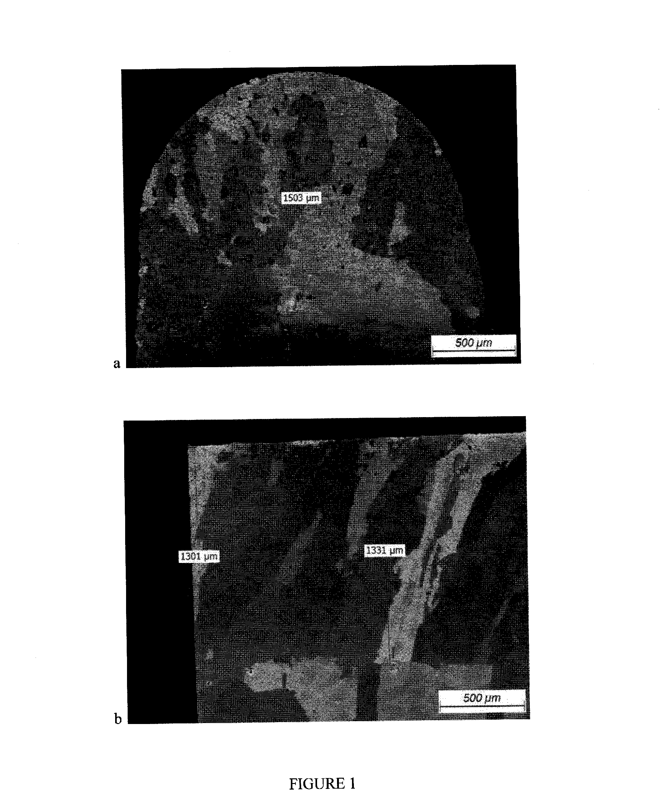
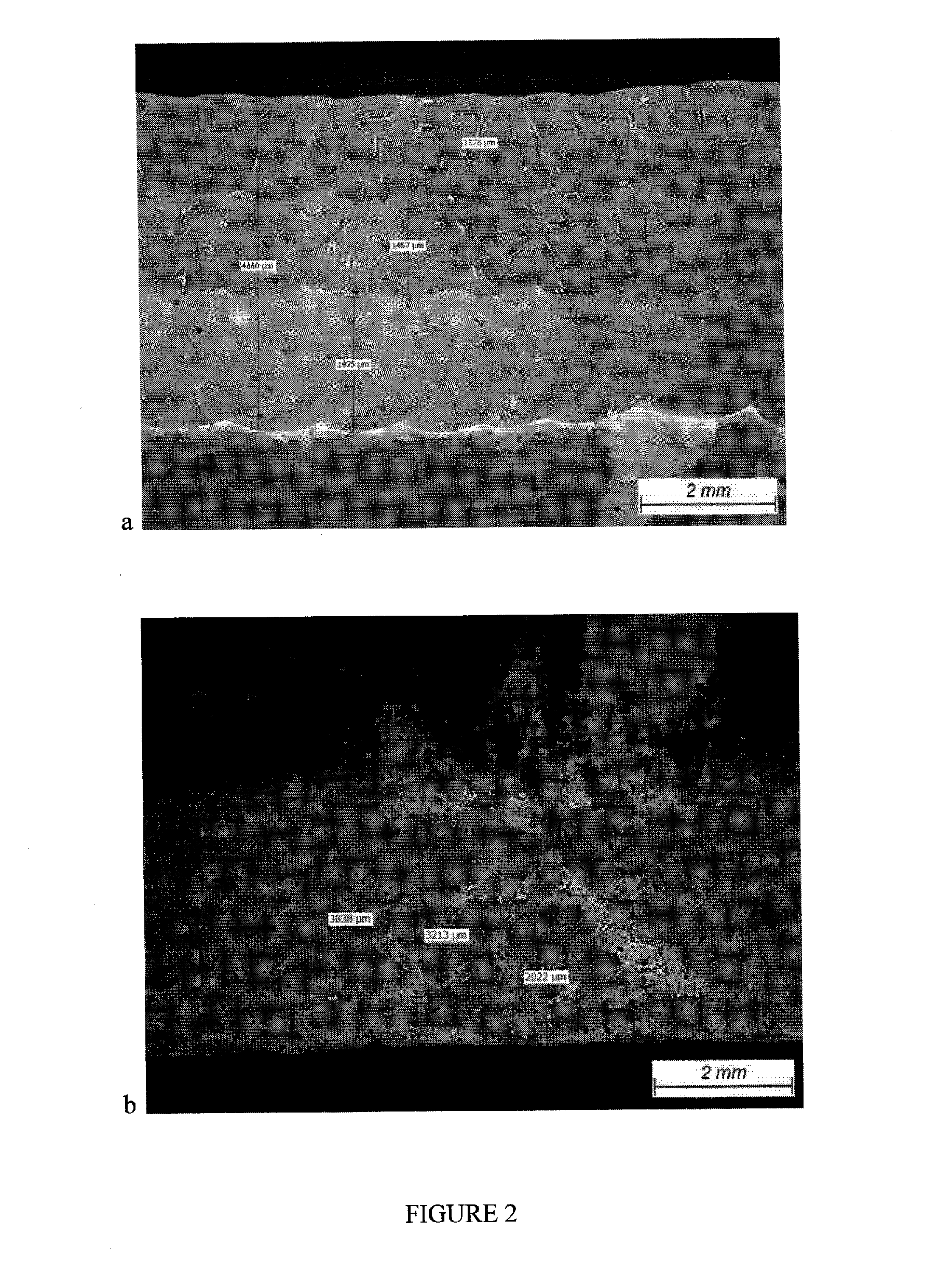
[0184]No cracks were observed in clad welds and HAZ. Typical micrographs of samples are shown in FIGS. 1...

example 2

[0185]Three (3) passes laser cladding was made at an ambient temperature using filler material comprised of 75% Inconel 738 high temperature filler and 25% AWS BNi-9 brazing powders on the Inconel 738 substrate of 0.080-0.090 inch in width at an ambient temperature.

[0186]To produce clad welds of 0.090-0.100 inch in width the laser welding head was oscillated perpendicular to the welding direction.

[0187]To minimize overheating of the substrate during the first pass and ensure good fusion between passes the laser beam power was incrementally increased from the first pass to the top (last) one.

[0188]Following below welding parameters were used:

Welding speed—3.8 ipm

Powder feed rate—6 g / min

Oscillation speed (across weld samples)—45 ipm

Oscillation distance—0.033 inch either side of the center line of the sample

Beam power: 325 W (first pass), 350 W (second pass), 400 W (third pass)

Carrier gas—argon

Shielding gas—argon

After welding samples were cut in two equal parts.

[0189]One part was subje...

example 3

[0192]Three (3) passes laser cladding was made at an ambient temperature using filler powder comprised of 73% Inconel 738 high temperature filler and 27% AWS BNi-9 brazing powders on the Mar 002 substrate of 0.080-0.090 inch in width.

[0193]To produce clad welds of 0.090-0.100 inch in width the laser head was oscillated perpendicular to the welding direction.

[0194]Following below welding parameters were used:

Welding speed—3.8 ipm

Powder feed rate—8 g / min

Oscillation speed (across weld samples)—45 ipm

Oscillation distance—0.033 inch either side of the center line of the sample

Beam power: 475 W for all three passes

Carrier gas—argon

Shielding gas—argon

[0195]Welded samples were subjected to a post-weld heat treatment in vacuum with a pressure below of 10−4 torr at a temperature of 1200°±10° C. for two (2) hours. At this temperature the material of the clad welds was in a solid—liquid condition that allowed self-healing of micro cracks in the welds. We observed the formation of the eutectoid ...


PUM

PropertyMeasurementUnit
diameteraaaaaaaaaa
temperatureaaaaaaaaaa
temperaturesaaaaaaaaaa

Abstract

The present concept is a method of substantially crack-free cladding, fusion welding and additive manufacturing of superalloys. The method involves the application of a high temperature pre-alloyed filler powder that includes melting point depressants, to a superalloy base material. The base material and pre-alloyed filler powder are heated to a temperature that will fully melt the pre-alloyed filler powder and also melt a surface layer of the base material, thereby forming a weld pool. Upon solidification and cooling of the weld pool, there is coalescence between a weld bead and the base material thereby forming the weld bead which is substantially crack-free. The high temperature pre-alloyed filler powder consists in wt % of the following chemical elements: Co 9-15%; Al 3-6.5%; C 0.1-0.2%; Ti, Zr and Hf with a total content from 1 to 8.5%; Ta and Nb with a total content from 0.5 to 8.5%; W and Mo with a total content from 7 to 20%; Cr and Re with a total content from 6.5 to 18.5%; Fe and Mn with a total content from 0.1 to 1%; B 0.1-0.6% with Ni and impurities to balance.

Description

[0001]The present invention is a continuation-in-part of regularly filed U.S. utility application Ser. No. 14 / 468,680 titled “METHOD OF CLADDING AND FUSION WELDING OF SUPERALLOYS” filed on Aug. 26, 2014 by Liburdi Engineering Limited, claiming priority from PCT application PCT / CA2012 / 001118, filed on Dec. 5, 2012.FIELD OF THE INVENTION[0002]The invention relates to fusion welding and filler materials for fusion welding and can be used for manufacturing and repair of turbine engine components made of nickel, cobalt and iron based superalloys utilizing gas tungsten arc welding (GTAW), laser beam (LBW), electron beam (EBW), plasma (PAW) and micro plasma (MPW) manual and automatic welding.[0003]Further refinements were discovered for improving the homogeneity of the welding pool, in particular for welding pools of small diameter and width, enabling the application of the invented method and materials for additive manufacturing (AM) utilizing cladding and powder bed processes. Previous i...

Claims


Application Information

Patent Timeline
Patent Type & Authority Applications(United States)
IPC IPC(8): B23K26/342B23K10/02B23K15/00B23K26/32
CPCB23K26/342B23K26/32B33Y10/00B23K15/0086B23K2201/001B23K10/027B23K1/0018B23K1/0056B23K9/042B23K9/23B23K35/0222B23K35/0233B23K35/0238B23K35/0244B23K35/0255B23K35/22B23K35/24B23K35/30B23K35/3033B23K35/304B23K35/3046B23K2101/001B23K2103/08B23K2103/18B23K2103/26C21D9/50C22F1/10F01D5/005F05D2230/232F05D2300/13
Inventor GONCHAROV, ALEXANDER B.LIBURDI, JOSEPHLOWDEN, PAULHASTIE, SCOTT
Owner LIBURDI ENG
Learn More