
Method for depositing metal-containing film using particle-reduction step

a metal-containing film and particle reduction technology, applied in the field of metal-containing film depositing method, can solve the problems of similar particle generation problem, difficult processing of process material, unavoidable particle generation, etc., and achieve the effect of reducing surface roughness, sufficient chemical resistance and mechanical strength, and simplifying process sequen

Inactive Publication Date: 2016-06-16
ASM IP HLDG BV
View PDF10 Cites 319 Cited by
  • Summary
  • Abstract
  • Description
  • Claims
  • Application Information

AI Technical Summary

Benefits of technology

This patent discusses a method for forming a metal oxide or nitride film on a substrate using plasma-enhanced atomic layer deposition (PEALD). The method addresses problems related to particle generation during the film formation process, even when highly reactive precursors and reactant gases are used. The method involves adjusting process temperature, controlling partial pressure of the reactant gas, and reducing impurities in the reactant gas. These measures significantly reduce the number of particles generated during the film formation process. The method also allows for controlled crystal grain formation and surface roughness of the film, resulting in a high-quality film with improved chemical resistance and mechanical strength. A suitable precursor and process temperature can also prevent premature dissociation of the precursor and reduce particle formation. Overall, the method simplifies the process sequence, improves productivity, and reduces particle generation.

Problems solved by technology

Thus, the process material is difficult to handle and causes a problem associated with the presence of a small amount of oxidizing component.
Also in atomic layer deposition (ALD), particle generation is a problem unavoidable when a process material and an oxidizing gas co-exist in the process.
As with an oxidizing gas, reactivity of a reactant gas used for nitridization against a precursor tends to cause a similar particle-generation problem.
However, such modifications of the sequence prolong the cycle duration, lowering productivity.

Method used


Image

  • Method for depositing metal-containing film using particle-reduction step
  • Method for depositing metal-containing film using particle-reduction step
  • Method for depositing metal-containing film using particle-reduction step

Examples


examples

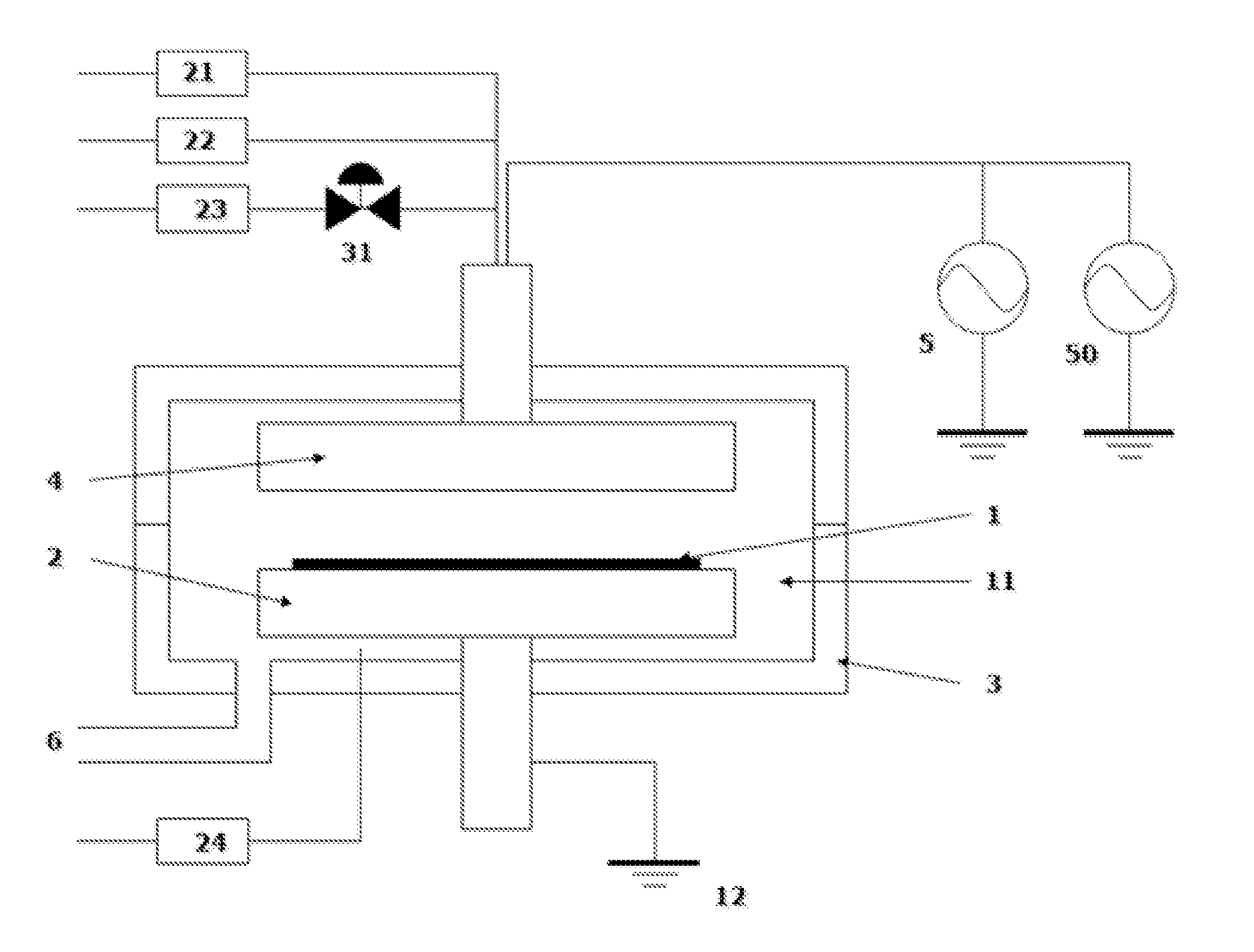
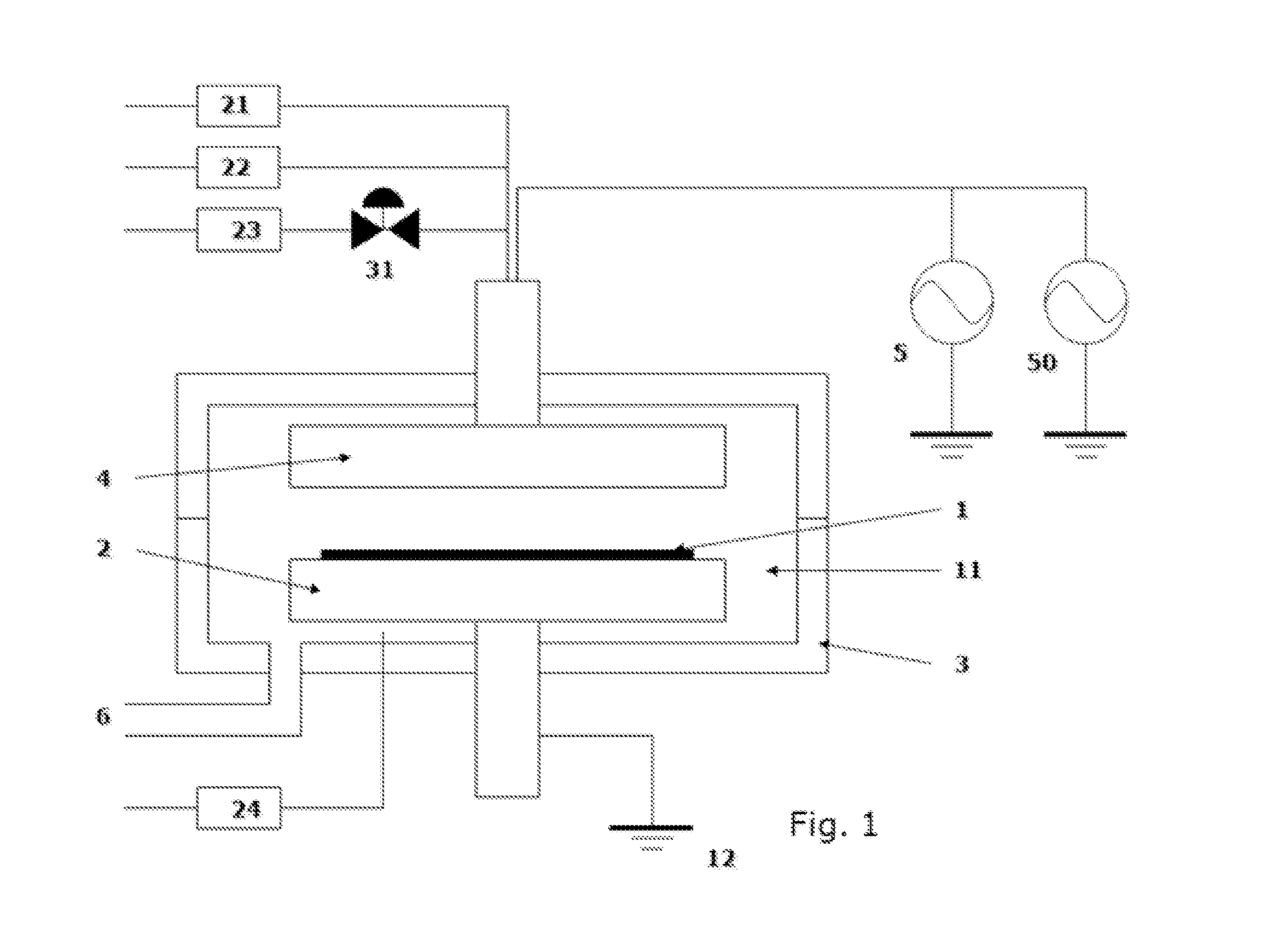
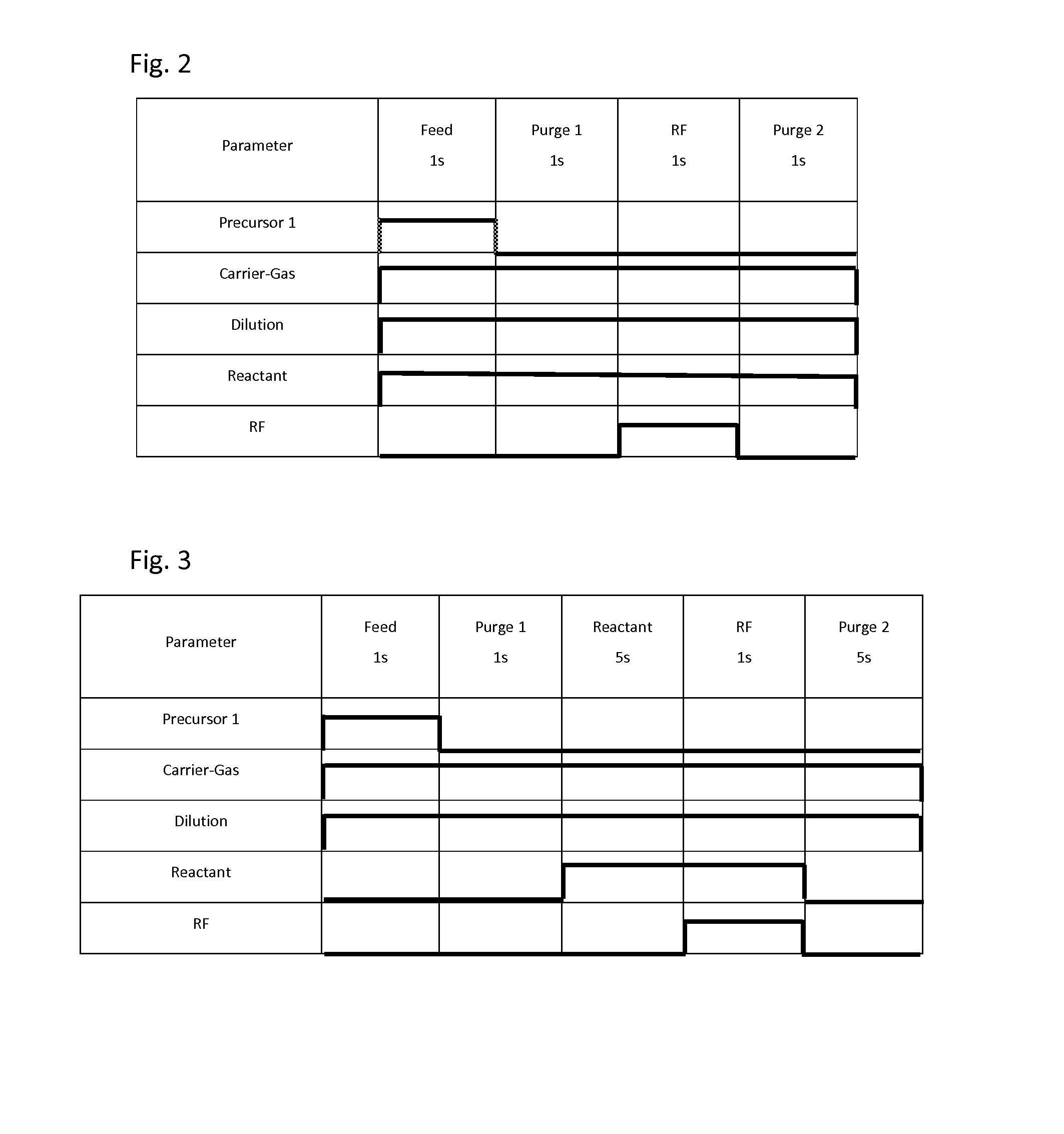
[0048]Metal-containing films were deposited on substrates having patterns (aspect ratio: 2:1) under common conditions shown in Table 2 or 3 below using the process sequence illustrated in FIG. 2 (continuous reactant flow) or FIG. 3 (pulsed reactant flow), and using the apparatus illustrated in FIG. 1. A precursor was fed to the reaction chamber using the flow-pass system illustrated in FIGS. 5A to 5C. For purifying gases, a Gas Clean () ST Purifier assembly (by Pall Corporation) was used, which was designed to remove contamination from many process gases, wherein sub ppb level purification was capable at designed flow rates of up to 5 slm while providing 0.003 μm filtration, and according to the technical information, it was capable of reducing impurities H2O, CO2, O2, and CO to less than 1 ppb from argon, nitrogen, and hydrogen. The purifiers were installed as illustrated in FIGS. 4A to 4C. For purifying gases, the carrier gas, dilution gas, and reactant gas passed through the puri...

examples 1 to 15

[0049]A metal oxide film was formed on a substrate (0300 mm) by PEALD under conditions shown in Table 4 below in addition to the above-described common conditions. The value (%) of O2 concentration (i.e., the partial pressure of O2) was rounded off to a natural number (no decimal place) (in some embodiments, the value is rounded off to one or two decimal places). Also, the O2 concentration when pulsed represents the concentration while being fed, not throughout the entire cycle. The growth rate per cycle (GPC) of each film was determined, and the obtained metal oxide film was evaluated in terms of the number of particles having a size of 0.1 μm or greater, and chemical resistance (wet etch rate in DHF at 100:1 as compared with thermal oxide film). The results are shown in Table 5 below.

TABLE 4O2TempConcentrationO2Ex.Precursor(° C.)(%)PurifierFlow 1*Tetrakis(dimethyl-amino)-Zr20017NoContinuous 2*Tetrakis(dimethyl-amino)-Zr20017NoContinuous 3*Tetrakis(dimethyl-amino)-Zr20017NoPulsed 4...

examples 16 to 22

[0052]A metal nitride film was formed on a substrate (0300 mm) by PEALD under conditions shown in Table 6 below in addition to the above-described common conditions. The growth rate per cycle (GPC) of each film was determined, and the obtained metal oxide film was evaluated in terms of the number of particles having a size of 0.1 μm or greater. The results are shown in Table 7 below.

TABLE 6N2 / H21)TempConcentrationN2 / H2Ex.Precursor(° C.)(%)PurifierFlow16*Tetrakis(dimethyl-amino)-Zr20017NoContinuous17*Tetrakis(dimethyl-amino)-Zr20017NoContinuous18*Tris(dimethyl-amino)-20017NoPulsedcyclopentadienyl-Zr19*Tris(dimethyl-amino)-20017NoContinuouscyclopentadienyl-Zr20Tris(dimethyl-amino)-20017YesContinuouscyclopentadienyl-Zr21Tris(dimethyl-amino)-2004NoContinuouscyclopentadienyl-Zr22Tris(dimethyl-amino)-20019YesContinuouscyclopentadienyl-Hf*denotes comparative examples.1)a flow ratio was 17% (N2 = 100 sccm; H2 = 600 sccm)

TABLE 7≧0.1 μmGPCEx.Particle(ea)(nm / cycle)16*234500.0517*252000.05518*1...


PUM

PropertyMeasurementUnit
temperatureaaaaaaaaaa
pressureaaaaaaaaaa
sizeaaaaaaaaaa

Abstract

A method for forming a metal oxide or nitride film on a substrate by plasma-enhanced atomic layer deposition (PEALD), includes: introducing an amino-based metal precursor in a pulse to a reaction space where a substrate is placed, using a carrier gas; and continuously introducing a reactant gas to the reaction space; applying RF power in a pulse to the reaction space wherein the pulse of the precursor and the pulse of RF power do not overlap, wherein conducted is at least either step (a) comprising passing the carrier gas through a purifier for reducing impurities before mixing the carrier gas with the precursor, or step (b) introducing the reactant gas at a flow rate such that a partial pressure of the reactant gas relative to the total gas flow provided in the reaction space is 15% or less.

Description

BACKGROUND OF THE INVENTION[0001]1. Field of the Invention[0002]The present invention generally relates to a method for depositing a film containing a metal such as a transition metal without increasing particle contamination.[0003]2. Description of the Related Art[0004]It is well known that a process material for forming a film containing Zr or Ti has strong reactivity to moisture or air. Thus, the process material is difficult to handle and causes a problem associated with the presence of a small amount of oxidizing component. For example, when forming a ZrO film by CVD, particles tend to be generated due to co-existence of a process material and an oxidizing gas. If particle generation is a problem in the process, it is required to control the co-existence state of the process material and the oxidizing gas by adjusting the location of gas inlets, method of introducing the gases, etc. Also in atomic layer deposition (ALD), particle generation is a problem unavoidable when a proce...

Claims


Application Information

Patent Timeline
Patent Type & Authority Applications(United States)
IPC IPC(8): C23C16/44C23C16/34C23C16/40C23C16/505C23C16/455
CPCC23C16/4402C23C16/505C23C16/4554C23C16/34C23C16/405C23C16/40C23C16/45553C23C16/45561
Inventor FUKAZAWA, ATSUKIFUKUDA, HIDEAKI
Owner ASM IP HLDG BV
Learn More