
Continuous reaction device for synthesizing polyoxymethylene dimethyl ethers

a technology of polyoxymethylene dimethyl ether and reaction device, which is applied in the field of energy resource chemical industry, can solve the problems of increasing the contradiction between petroleum supply and relatively fast sustaining development of economics and society, the gradual decrease of the cetane number (cn value) of diesel fuel products, and the significant increase of noxious substances discharged after combustion. , to achieve the effect of reducing the total energy consumption of the stirring mixing process, saving energy, and high mixing efficiency

Inactive Publication Date: 2016-06-30
DONGFANG HONGSHENG NEW ENERGY APPL TECH RES INST +1
View PDF0 Cites 3 Cited by
  • Summary
  • Abstract
  • Description
  • Claims
  • Application Information

AI Technical Summary

Benefits of technology

The present invention provides a reaction device configuration and an optimized operation mode that can increase the rate of chemical reactions and the yield of target products, as well as improve the selectivity of certain substances. This is based on the characteristics of the reaction mixture, which help to optimize the reaction process on a large scale for industrialization.

Problems solved by technology

Traditionally, diesel fuel production relies upon petroleum feedstock, and the resource endowment of China characterized in relatively “rich in coal, poor in oil, and lack in gas” leads to increasingly prominent contradiction between petroleum supply and relatively fast sustaining development of economics and society.
Furthermore, the worsening of crude oil quality leads to continuous scale expansion of domestic catalytic processing of heavy oil and increasing percentage of diesel fuel produced by catalytic processing, which results in gradual decrease of the cetane number (CN value) of diesel fuel products and significant increase of noxious substance discharged after combustion, therefore, the urgent problem to be solved is to increase the CN value of diesel fuel.
Furthermore, there is also limited evidence indicating that, inhaling diesel engine tail gas is relevant to suffering from bladder cancer.
However, as calculated according to data provided by its embodiments, the total cross-section linear speed in the reaction tube appears to be very low, and there is no description of whether the two phases can be mixed sufficiently or whether the dispersion phase can be dispersed sufficiently.
Furthermore, although the main reaction is a series of reversible exothermic reactions, because of the restriction of reaction kinetics, with a limited heat release rate per unit effective reactor volume during a unit period of time, it remains a question whether a very large specific area for heat exchange is required.
Apparently, the stirred tank reactor / membrane separation apparatus as a whole is still using batch operation, which adversely affects the process intensity and is disadvantageous for large-scale implementation of a single series of equipments.
However, it is found out during implementation that, the experiments carried out by using paraformaldehyde and methylal as feedstock or using trioxane and methylal as feedstock in the presence of all kinds of acidic catalysts under pressurized condition all involve a system of slow solid-solid-liquid, solid-liquid or liquid-liquid complicated heterogeneous catalytic reaction, which leads to that the chemical reaction rate is always very low in the general processes and that the reaction is generally required to last for hours or even longer.
Therefore, the R&D of a suitable reaction device has become one of the key factors limiting large-scale industrialization of this technology.

Method used


Image

  • Continuous reaction device for synthesizing polyoxymethylene dimethyl ethers
  • Continuous reaction device for synthesizing polyoxymethylene dimethyl ethers
  • Continuous reaction device for synthesizing polyoxymethylene dimethyl ethers

Examples


embodiment 1

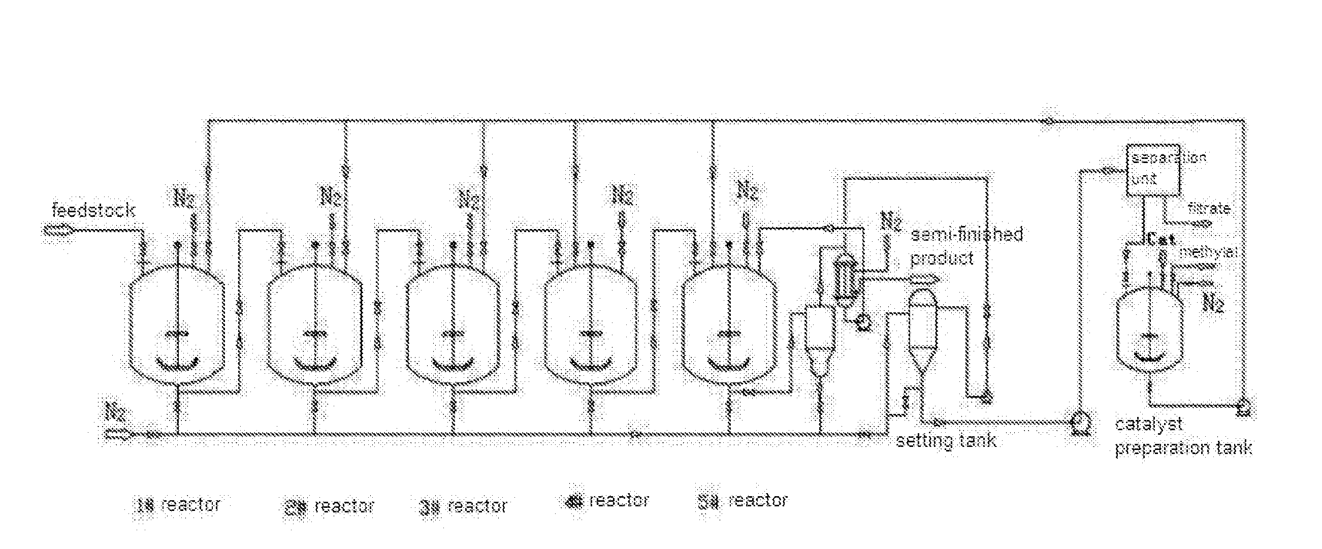
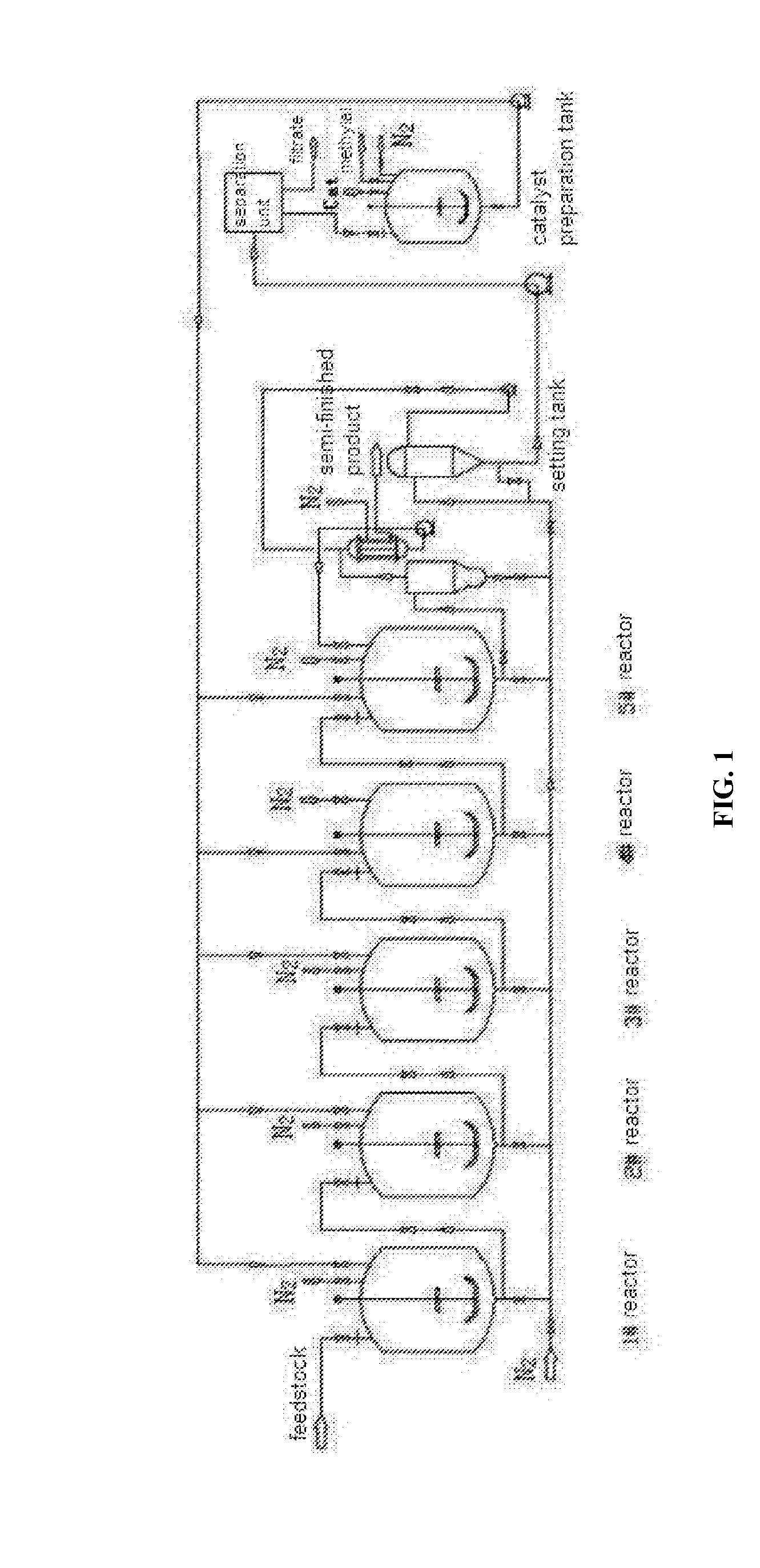
[0046]As shown in FIG. 1, an reaction device for catalytically synthesizing polyoxymethylene dimethyl ethers from paraformaldehyde powder and methylal as feedstock comprises 5 slurry bed stirred tank reactors connected in series. Each reactor has a volume of 0.5 m3 and a volume filling coefficient of 0.8. Each reactor is provided with a half-pipe heat exchanger wound around an outside of a barrel of the reactor for serving as a heater when starting operation as well as a cooler during normal operation. The first 2-4 reactors are provided with pipe bundles or coiled pipes arranged at the inside thereof for serving as coolers during normal operation. Each reactor has a heat exchange area of about 3 m3. Each of the tank reactors is provided with an axial-flow stirring paddle having 2-6 blades per layer, to ensure sufficient mixing of the reaction mixture.

[0047]An on-line solid-liquid separation device is provided after the last one of the tank reactors, to perform the separation of the...

embodiment 2

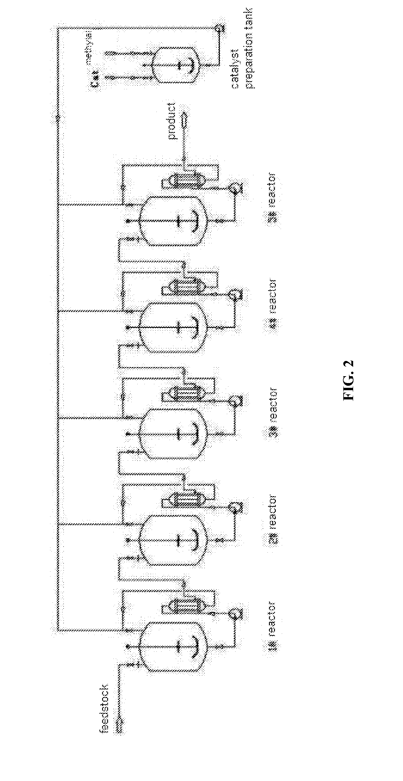
[0051]As shown in FIG. 2, an reaction device for catalytically synthesizing polyoxymethylene dimethyl ethers from sufficiently pre-depolymerized paraformaldehyde and methylal as feedstock comprises 7 slurry bed stirred tank reactors connected in series (only the connection apparatus of the first 5 reactors are shown). The configuration, geometric dimensions, operation pattern and entire reaction conditions of each of the reactors are the same as Embodiment 1. A difference in operation pressure between two adjacent ones of the tank reactors is utilized as a driving force of filtering, to achieve transport of the reaction mixture.

[0052]An on-line solid-liquid separation device is provided outside each of the reactors, to perform the separation of the reaction mixture from the catalyst. The on-line solid-liquid separation device is a multitubular filter performing on-line cross-flow filtering. A difference in operation pressure between two adjacent ones of the reactors is utilized as a...

embodiment 3

[0055]The reaction device of this embodiment comprises 7 slurry bed stirred tank reactors which are numbered Reactor No. 1-7. Counting from the feed end, Reactors No. 1 and No. 2 are connected in series to form a Unit 1, Reactors No. 3 and No. 4 are connected in series to form a Unit 2, and the Unit 1 and Unit 2 are then connected in parallel to form a Unit 3 which is further connected in series with Reactors No. 5, No. 6 and No. 7. The reaction system and feedstock are the same as Embodiment 1, and the configuration and geometric dimensions of various reactors, operation pattern and operation conditions of each reactor are all the same as Embodiment 1.

[0056]The difference only lies in that, two halves of the total flow of feedstock is respectively fed into Reactor No. 1 and Reactor No. 3, and the mass streams flowing out of Reactor No. 2 and Reactor No. 4 are converged and then fed into Reactor No. 5 and then into Reactor No. 6 and then into Reactor No. 7 successively. After a stea...


PUM

PropertyMeasurementUnit
temperatureaaaaaaaaaa
boiling pointaaaaaaaaaa
flash pointaaaaaaaaaa

Abstract

The present invention pertains to the technical field of energy resource chemical industry, and in particular relates to a continuous reaction device and process for synthesizing polyoxymethylene dimethyl ethers by using paraformaldehyde and methylal as feedstock or using trioxane and methylal as feedstock in the presence of an acidic catalyst. The continuous reaction device comprises multiple slurry bed stirred tank reactors connected in series or in combination of series connection and parallel connection, and also comprises an on-line solid-liquid separation device to perform separation of the reaction mixture from the catalyst. Each of the tank reactors is provided with an axial-flow stirring paddle having 2-6 blades per layer, to ensure sufficient mixing of the reactants with the catalyst. By using a distributed control pattern of reaction temperature and feedstock supplying to enhance the process and to optimize the operation, the reaction device of the present invention can effectively achieve large-scale continuous production of polyoxymethylene dimethyl ethers, and both the yield rates and the distribution of the reaction product are better than those of prior art.

Description

TECHNICAL FIELD[0001]The present invention pertains to the technical field of energy resource chemical industry, and in particular relates to a continuous reaction device for synthesizing polyoxymethylene dimethyl ethers.BACKGROUND OF THE INVENTION[0002]In recent years, phenomenon of short supply of diesel fuel frequently occurred in China, and its fundamental reason is the restriction of resource shortage. Traditionally, diesel fuel production relies upon petroleum feedstock, and the resource endowment of China characterized in relatively “rich in coal, poor in oil, and lack in gas” leads to increasingly prominent contradiction between petroleum supply and relatively fast sustaining development of economics and society. Since the year 1993 when China became a net importer of petroleum, the import volume has been increasing fast and constantly, and the foreign-trade dependence already surpassed 56% after 2011, which has a severe influence on national strategic security of energy.[00...

Claims


Application Information

Patent Timeline
Patent Type & Authority Applications(United States)
IPC IPC(8): C08G65/00B01J8/08B01J8/10
CPCC08G65/00B01J8/10B01J8/082B01J2208/00867B01J2208/00212B01J2208/00548B01J8/087C07C41/56C07C43/30B01J8/085B01J19/1862B01J8/006B01J8/0085B01J2208/00132B01J2208/00141B01J2208/00194B01J2208/00539B01J2208/00557B01J2208/00628
Inventor SHANG, HONGYANHONG, ZHENGPENGLI, CHENGYUEFENG, XIAOTINGHAN, YUXUE, ZHENZHEN
Owner DONGFANG HONGSHENG NEW ENERGY APPL TECH RES INST
Learn More