
Fluorescense-detected assays on microfluidic chips

Pending Publication Date: 2017-01-19
1DROP SA
View PDF6 Cites 10 Cited by
  • Summary
  • Abstract
  • Description
  • Claims
  • Application Information

AI Technical Summary

Benefits of technology

The invention provides an assay unit and a diagnostic device that have improved test sensitivity and precision, and use excitation power efficiently. The device uses an evanescent field to excite fluorescing molecules without losing significant light power. This allows for multiple microfluidic channels with uniform excitation, with only one waveguide structure. The device is also cost-effective and easy to manufacture. The technical effects are improved accuracy and precision of fluorescence-detected assay tests, as well as a more reliable and uniform excitation light field.

Problems solved by technology

However, they also have the disadvantage of being expensive, and requiring well trained personnel for operation.
However, since such devices require a physiological sample from a patient, said samples have to be transported to the medical laboratory, where the analysis is going to be performed, and have to be handled and stored appropriately.
Current point-of-care diagnostics devices are often not accurate or sensitive enough to be relied on as the only source of information.
One challenge therefore is to develop point-of-care diagnostics devices that are sensitive and accurate enough to provide an equal alternative to clinical laboratories.
While these microfluidic chips are powerful, they are still expensive to manufacture in silicon, and they require an expensive high-end fluorescence microscope for optical signal acquisition and quantification.
Despite their many benefits, high-sensitivity fluorescence detection systems also have several limitations.
A large optical reader system is usually needed, with a large and complex optical train, typically employing confocal laser scanning microscopy.
Additionally, many of the described systems have very limited fluidic control, requiring trained personnel for pipetting, or pipetting robots, or active pumping.
Furthermore, biochemical reactions on surfaces and in large reaction vessels, have large diffusion distances, causing them to operate in a transport-limited regime.
These combined limitations mean that highly sensitive fluorescence detection is uncommon in point-of-care diagnostics.
One of the key remaining challenges is the miniaturization of the instrumentation for signal readout without a decrease in performance.
As a consequence a large fraction of the excitation power usually remains unused, thus artificially decreasing the local power density of excitation for the fluorophores or, its corollary, increasing the total amount of excitation power required.
This generates a large amount of unwanted light that decreases the overall signal to noise ratio.
The use of very high quality filters might become necessary to achieve acceptable S / N, thus increasing the total cost of the system.
Third, the existence of excitation light outside of the detection regions can be detrimental to the S / N through the generation of parasitic fluorescence emission.
Nevertheless, such a system does also suffer from two main drawbacks.
First of all, the absence of appropriate filtering functions in the microfluidic device imposes the use of pre-processed biological fluids, thus excluding the use of the device outside of the laboratory.
Second, the microfluidic layers need to be pealed before rinsing and imaging the fluorescent spots.
These operations are prohibitive to applying this method in a point-of-care device.
In the disclosed microfluidic chip, the high degree of photonic integration (secondary laser source, grating and waveguides) creates a high level of complexity in the chip fabrication that is not favourable for the use of such microfluidic chips in a practical point-of-care scenario.
First the in-print of DBG in PMMA is a rather fault intolerant process that is complicated to perform consistently in large series.
Since the later display high sensitivity to fabrication, environment and operation conditions, low measurement accuracy has to be expected.
This rules out the possibility of using such a system in a disposable chip based point-of-care scenario.
A second major drawback comes from the disruption of the waveguide by the microfluidic channel.
In these conditions a significant amount of excitation light is expected to emerge from the sidewalls of the microfluidic chip and then be collected by the final imaging system, which considerably decreases the signal-to-noise ratio due to parasitic scattering.
Since the loss of light is also caused by scattering of the light in the heterogeneous sample liquid, the resulting attenuation effect of the microfluidic channel is not reproducible, which renders the remaining excitation light essentially useless for further quantitative measurements.
The dimensions and materials needed for the disclosed system are unsuited for current mass fabrication methods in plastics such as injection moulding.
With whole blood as sample however there is a high chance to clog the interaction volume, since whole blood filtering cannot always remove all cellular components.
Implementing the described method into passive microfluidic systems is very difficult.
First, the use of a slab waveguide / one-dimensional guiding layer has a negative effect on the overall excitation efficiency, which can be inferior by orders of magnitude, due to the lack of lateral confinement.
Thus the disclosed setup can be expected to be unsuitable and not being properly functioning for longer distances between excitation light entry and assay site, particularly because also detection takes place via the slab waveguide, further decreasing the available light signal.
Second, the use of materials such as SiN and SiO2 is prohibitive for the realization of inexpensive disposable devices.
This approach is not only very inefficient with respect to the total amount of fluorescence light emitted, it does not provide any spatial discrimination.
This approach might therefore suffer from unwanted signal emanating from regions outside of the reaction region.
It also prohibits the use of such a system for multiplexed applications, since any distinct assay area would couple its fluorescence signal into the same waveguide layer, without the possibility to distinguish certain signal parts from each other.

Method used


Image

  • Fluorescense-detected assays on microfluidic chips
  • Fluorescense-detected assays on microfluidic chips
  • Fluorescense-detected assays on microfluidic chips

Examples


Embodiment Construction

[0104]The examples provided hereinafter serve an improved illustration of the present invention, but are not suited for restricting the invention to the features disclosed herein. Components that are identical, or that are identical at least in terms of their function, are designated below by identical or at least comparable reference numbers.

[0105]The invention will be described using the fluorescence-detected immunoassay as an example for an fluorescence-detected assay test. However, as it is clear for a person skilled in the art, the invention can be realized with any other fluorescence-detected assay technique where fluorophores are permanently, or at some stage of the analytical process, immobilized on a surface. Thus the described embodiments of fluorescence-detected immunoassays on microfluidic chips shall represent only an illustrative example, and are not intended to restrict the invention to this specific type of assay.

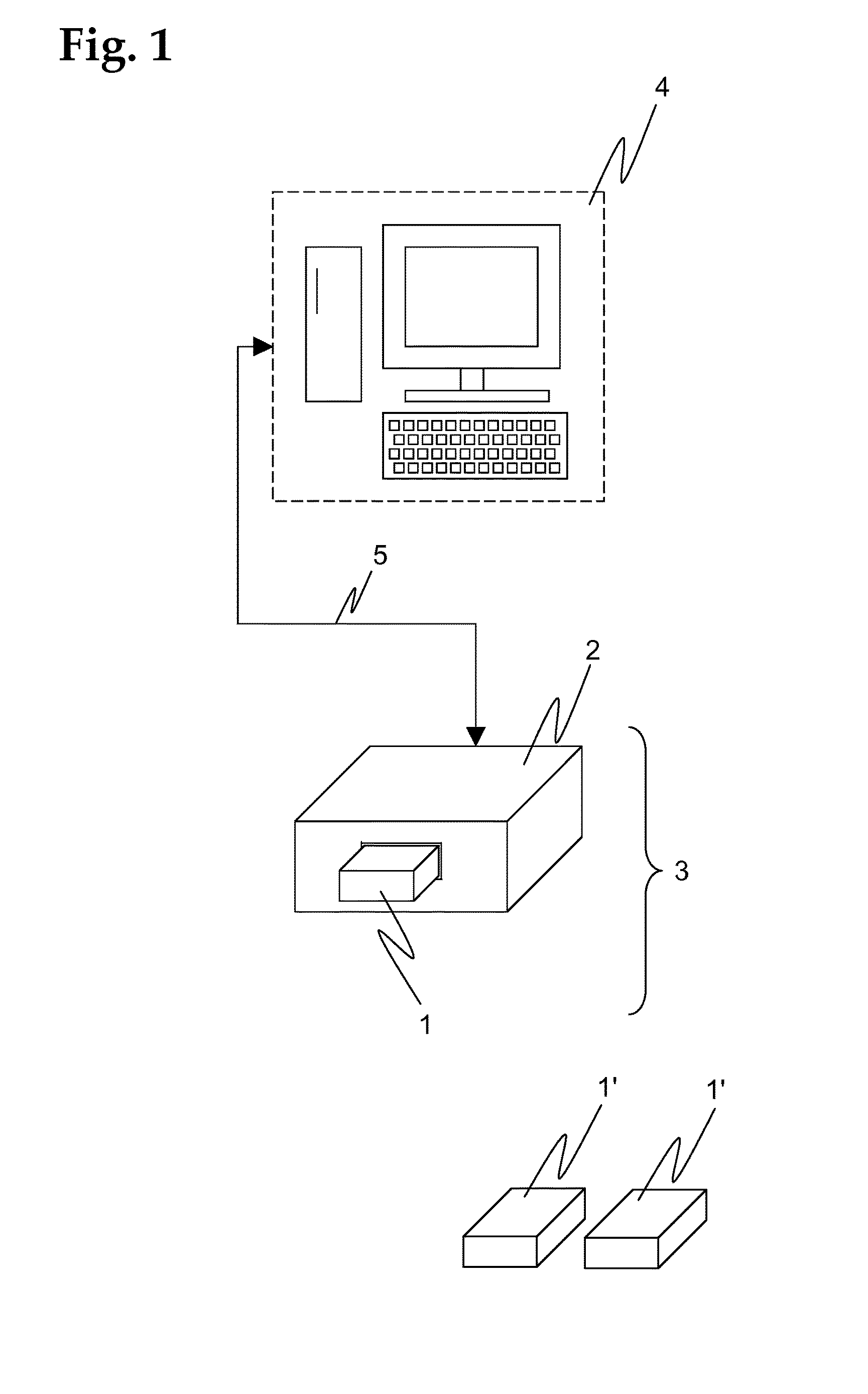
[0106]An exemplary embodiment of a diagnostic device 3...


PUM


Abstract

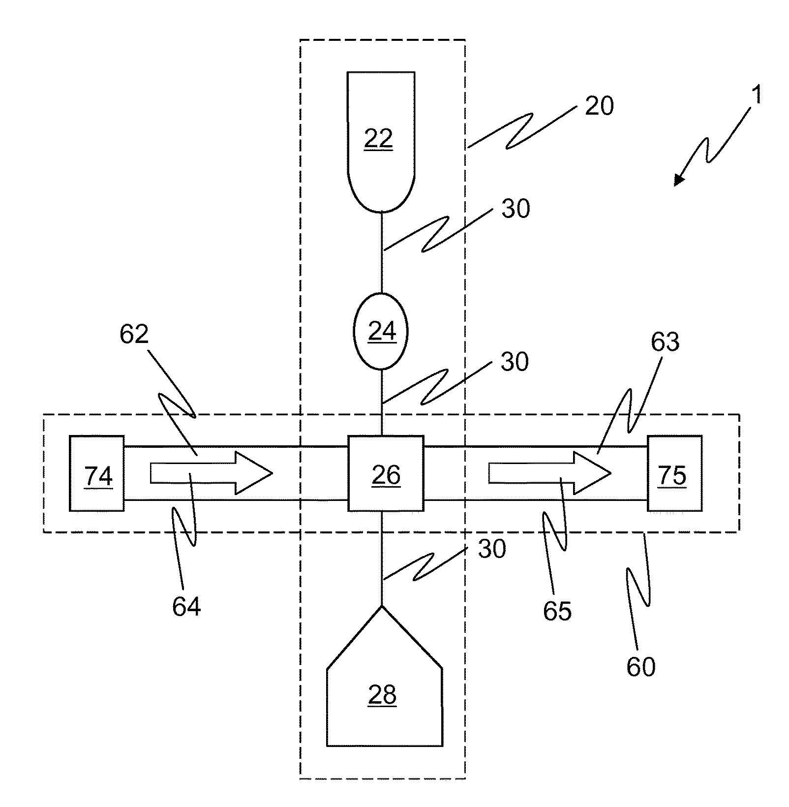
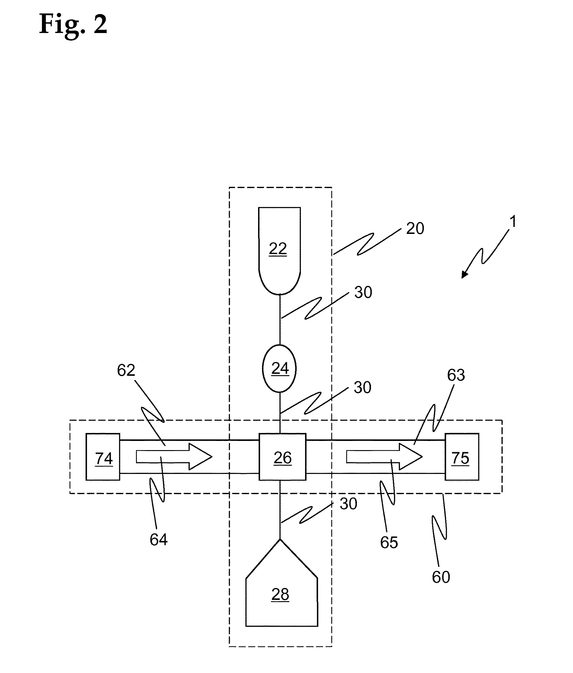
An assay unit for carrying-out fluorescence-detected assays on physiological samples comprises a microfluidic chip with a microfluidic system to convey a physiological sample or analyte solution through one or more microfluidic channels arranged on the chip, and a photonic system with two or more rectangular waveguide structures arranged on the chip to guide excitation light in the near IR, visible, or near UV range. The microfluidic channels and the waveguide structures cross each other at a detection site. In an assay area, where a certain microfluidic channel and a certain waveguide structure cross each other, one or more lateral surfaces of the core of the waveguide structure at least partially face an inner volume of the microfluidic channel, such that an evanescent field of light guided within the waveguide structure overlaps with a certain part of the inner volume of the microfluidic channel. In the assay areas, one or more capture spots are located on the surface of the waveguide core, the capture spots comprising a coating of capture antibodies of the immunoassay, immobilized on said core surface.

Description

BACKGROUND OF THE INVENTION[0001]Field of the Invention[0002]The invention relates to assay units for carrying out fluorescence-detected assays, reader units for reading the results of such assay units, and diagnostic devices with such assay units and reader units, according to the preamble of the independent claims.[0003]Discussion of Related Art[0004]Physiological samples such as for example body fluids may be analyzed for a wide variety of biochemical analytes. Accurate medical diagnostics is an important part of medical treatment such as the identification of health conditions and disease, monitoring, prognosis, and companion diagnostics. There are two main settings in which medical diagnostics systems are used: dedicated medical laboratories and the so-called point-of-care (PoC) testing.[0005]The term “physiological sample” in the context of this description shall comprise all material that is either biological material obtained from the patient, such as blood, urine, stool, or...

Claims


Application Information

Patent Timeline
IPC IPC(8): G01N21/64G01N33/543B01L3/00G01N21/77
CPCG01N21/648G01N21/7746G01N21/6428G01N33/54306B01L3/502715B01L2300/0816G01N2021/7786G01N2201/08B01L2300/0627B01L2300/0887G01N2021/6439G01N21/7703G01N2021/7736B01L2300/0654B01L2300/0877
Inventor GERVAIS, LUCZIEGLER, JORGDESCHARMES, NICOLAS
Owner 1DROP SA
Learn More