Method And System For Electrochemical Production Of Formic Acid From Carbon Dioxide

a technology of carbon dioxide and electrochemical production, applied in the field of electrochemistry, can solve the problems of inability to achieve faradaic efficiency greater than 32% in constant voltage experiments, too small for practical use, and different columbic efficiency from faradaic efficiency, so as to increase faradaic efficiency and lower voltage

Active Publication Date: 2017-02-09
DIOXIDE MATERIALS
View PDF5 Cites 87 Cited by
  • Summary
  • Abstract
  • Description
  • Claims
  • Application Information

AI Technical Summary

Benefits of technology

[0027]An anion exchange membrane can be directly positioned between a gas diffusion electrode (GDE) cathode structure and the central flow compartment. The GDE cathode structure can contain an anion exchange polymer that can work in conjunction with the anion exchange membrane in promoting the cathodic reduction of CO2 to formic acid. CO2 is reduced to formate ions (HCOO−) at the cathode GDE electrocatalyst layer (CL). The utilization of an anion exchange membrane, which does not permit the bulk flow of liquid to the GDE, provides that the gas diffusion electrode (GDE) structure does not flood under the aqueous liquid hydrostatic pressure of the aqueous formic acid solution formed in the central flow compartment. The anion exchange membrane can allow for the transport of the formate ions generated in the GDE catalyst layer through the membrane and into the central flow compartment. The anion membrane also can allow for the transport of water to the GDE catalyst layer through the membrane. The CO2 supplied to the GDE cathode can preferably be suitably humidified with water vapor, such that the membrane in contact with the CL stays sufficiently hydrated during electrochemical operation.
[0030]The central flow compartment can be a thin, empty compartment for collecting the formic acid product, or preferably, can contain either an ion conductive fill material such as a weak or strong acid cation exchange material or a strong base anion exchange material. The preferable ion conducting material would help promote the transport of H+ ions as well as the formate ions in the formation of formic acid, as well as providing a suitable ionic conductivity in the central flow compartment to reduce the voltage drop of the compartment.
[0106]Helper Membranes are related to the Helper Catalysts described in earlier U.S. patent application Ser. Nos. 12 / 830,338 and 13 / 174,365, international application No. PCT / US2011 / 042809, and U.S. Pat. No. 8,956,990. Examples of Helper Membranes are disclosed in co-owned U.S. Pat. No. 9,370,773, which is hereby incorporated by reference. Helper Membranes, like the disclosed Helper Catalysts, can increase the Faradaic efficiency and allow significant currents to be employed at lower voltages.

Problems solved by technology

However, a system in which the Faradaic efficiency in a constant voltage experiment is greater than 32% has not been achieved.
Furthermore, the reported rates of CO2 conversion current (calculated as the product of the Faradaic efficiency for CO2 conversion and the current in the cell after 30 minutes of operation) have been less than 5 mA / cm2, which is too small for practical uses.
However columbic efficiency is different from Faradaic efficiency.
The application states that a “system can provide selectivity of methanol as part of the organic product mixture, with a 30% to 95% Faradaic yield for carbon dioxide to methanol, with the remainder evolving hydrogen.” However, the application does not provide data demonstrating a 30% to 95% Faradaic yield.
In conclusion, Faradaic efficiencies of less than 30% are not practical.
Furthermore, a device with a low CO2 conversion current is impractical.

Method used


Image

  • Method And System For Electrochemical Production Of Formic Acid From Carbon Dioxide
  • Method And System For Electrochemical Production Of Formic Acid From Carbon Dioxide
  • Method And System For Electrochemical Production Of Formic Acid From Carbon Dioxide

Examples


specific example 1

[0247]Specific Example 1 illustrates a procedure to create an electrolyzer with a Helper Membrane. The embodiment of Specific Example 1 demonstrates improved performance over earlier electrochemical cells used for CO2 conversion.

[0248]Measurements were conducted in an electrolysis cell with an anode, cathode, and anion-conducting polymer electrolyte membrane held in Fuel Cell Technologies 5 cm2 fuel cell hardware assembly with serpentine flow fields.

[0249]The cathode in Specific Example 1 was prepared as follows. Silver ink was made by mixing 30 mg of silver nanoparticles (20-40 nm, 45509, Alfa Aesar, Ward Hill, Mass.) with 0.1 ml deionized water (18.2 Mohm, EMD Millipore, Billerica, Mass.) and 0.2 ml isopropanol (3032-16, Macron Fine Chemicals, Avantor Performance Materials, Center Valley, Pa.). The mixture was then sonicated for 1 minute. The silver ink was then hand-painted onto a gas diffusion layer (Signet 35 BC GDL, Ion Power Inc., New Castle, Del.) covering an area of 2.5 cm×...

specific example 2

[0284]The object of this example was to determine whether changes in the membrane doping could activate a membrane for CO2 conversion. AMI-7001 and CMI-7000 were chosen as test examples since they have the same polystyrene backbone as in PSMMIM and PSDMIM, but different amine groups, so they might be able to be activated.

[0285]The AMI-7001 was pretreated by soaking the membrane in a 1 M NaCl solution for one hour, followed by soaking in water for about 3 hours.

[0286]The selectivity rose to 70%. The current density was still low (3.5 mA / cm2). So this membrane is still not a Helper Membrane but its performance is much better.

[0287]The CMI-7000 was pretreated using the same procedure. Again, the selectivity rose to 72%. The current density was still low (15 mA / cm2).

[0288]Still, it is possible that the current could be raised if thinner membranes were made with the same bulk composition as AMI-7001 and CMI-7000, and then the membranes were doped with NaCl. Such a membrane could be a Hel...

specific example 3

[0289]The objective of Specific Example 3 is to provide another example of a Helper Membrane.

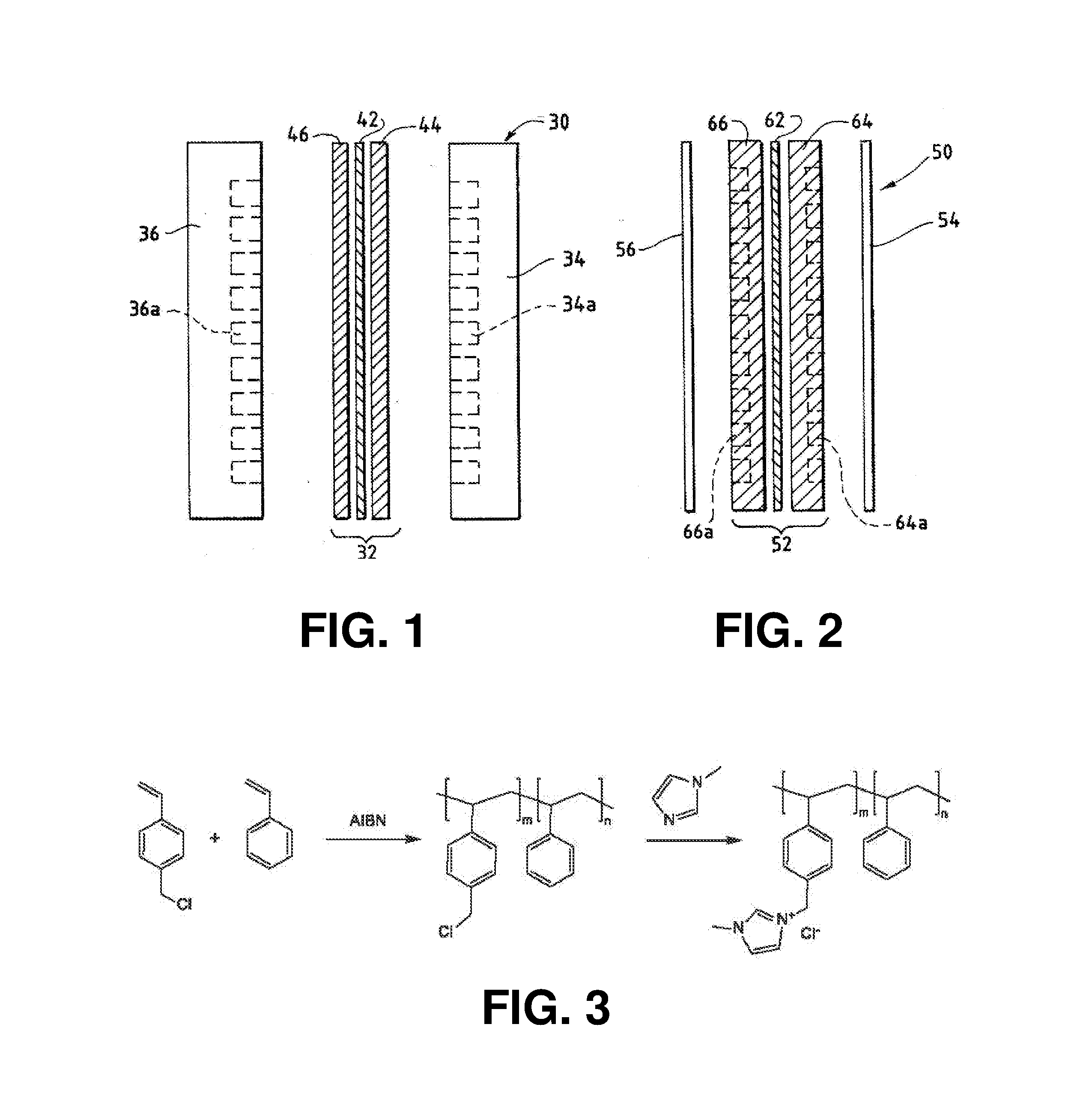
[0290]Preparation of PSDMIM: Poly(4-vinylbenzyl chloride-co-styrene) was prepared as in Specific Example 2. 1,2-dimethylimiazole (Sigma-Aldrich) (2.8455 g, 0.0296 mol) is added to the solution of the poly(4-VBC-co-St) (5.0907 g) in anhydrous N,N-Dimethylformamide (DMF) (Sigma-Aldrich) (30 ml). The mixture was stirred at room temperature for 0.5-1 hour, and then heated at 110-120° C. for 66.92 hours. PSDMIM was obtained as a yellowish solid after purification by precipitation into diethyl ether.

[0291]A PSDMIM membrane was formed as in Specific Example 2. Then the membrane was tested as in Specific Example 1. The results are given in Table 2 below. PSDMIM refers to a co-polymer of styrene and 1-(p-vinylbenzyl)-2,3-dimethyl-imidazolium:

where X− is an anion and m>0 and n>0.


PUM

PropertyMeasurementUnit
temperatureaaaaaaaaaa
current densityaaaaaaaaaa
thicknessaaaaaaaaaa

Abstract

An electrochemical device converts carbon dioxide to a formic acid reaction product. The device includes an anode and a cathode, each comprising a quantity of catalyst. The anode and cathode each have reactant introduced thereto. Two membranes, a cation exchange polymer electrolyte membrane and an anion exchange polymer electrolyte membrane, are interposed between the anode and the cathode, forming a central flow compartment where a carbon dioxide reduction product, such as formic acid, can be recovered. At least a portion of the cathode catalyst is directly exposed to gaseous carbon dioxide during electrolysis. The average current density at the membrane is at least 20 mA / cm2, measured as the area of the cathode gas diffusion layer that is covered by catalyst, and formate ion selectivity is at least 50% at a cell potential difference of 3.0 V. In some embodiments, at least one polymer electrolyte membrane comprises a polymer in which a constituent monomer is (p-vinylbenzyl)-R, where R is selected from the group consisting of imidazoliums, pyridiniums and phosphoniums. In some embodiments, the polymer electrolyte membrane is a Helper Membrane comprising a polymer containing an imidazolium ligand, a pyridinium ligand, or a phosphonium ligand.

Description

CROSS-REFERENCE TO RELATED APPLICATIONS[0001]The present application is a continuation-in-part of U.S. non-provisional patent application Ser. No. 14 / 704,934, filed on May 5, 2015, entitled “Electrochemical Device for Converting Carbon Dioxide to a Reaction Product”. The '934 non-provisional application is a continuation-in-part of International Application No. PCT / US2015 / 14328, filed on Feb. 3, 2015, entitled “Electrolyzer and Membranes”. The '328 international application also claimed priority benefits from U.S. provisional patent application Ser. No. 62 / 066,823, filed on Oct. 21, 2014.[0002]The '934 non-provisional application is also a continuation-in-part of International Application No. PCT / US2015 / 26507, filed on Apr. 17, 2015, entitled “Electrolyzer and Membranes”. The '507 international application is a continuation-in-part of the '328 international application. The '934 non-provisional application also claims priority benefits from the '823 provisional application.[0003]The...

Claims


Application Information

Patent Timeline
Patent Type & Authority Applications(United States)
IPC IPC(8): C25B3/04C25B15/02C25B15/08C25B1/02C25B9/10C25B3/25C25B9/19C25B9/23
CPCC25B3/04C25B1/02C25B15/02C25B15/08C25B9/10B01J41/14C25B13/08H01M2300/0082C25B1/00C25B1/04H01M8/1023H01M8/1053H01M4/8668B01J47/12Y02E60/36Y02P70/50Y02E60/50C25B9/23C25B3/25C25B9/19
Inventor KACZUR, JERRY J.YANG, HONGZHOUSAJJAD, SYED DAWARMASEL, RICHARD I.
Owner DIOXIDE MATERIALS
Why Eureka
Try Eureka