Carbonate Precursors for Lithium Nickel Manganese Cobalt Oxide Cathode Material and the Method of Making Same

a lithium nickel manganese cobalt oxide and precursor material technology, applied in the direction of nickel compounds, cell components, transportation and packaging, etc., can solve the problems of relative scarcity of co resources, relative high cost of cobalt metal, and serious drawbacks of lco, so as to reduce the energy density of the battery

Active Publication Date: 2017-10-26
UMICORE AG & CO KG +1
View PDF2 Cites 9 Cited by
  • Summary
  • Abstract
  • Description
  • Claims
  • Application Information

AI Technical Summary

Benefits of technology

[0032]the lower tap density of the precursor yielding a lower tap density of the final product with a decrease of energy density in the battery as a consequence.

Problems solved by technology

LCO however also has serious drawbacks.
A main drawback is the relative scarcity of Co resources related to the relatively high cost of cobalt metal.
Still worse, historically the cobalt prize shows wild fluctuations, and these fluctuations possibly increased the need to find substitutes for LiCoO2.
However, the conventional carbonate precursor producing method is a precipitation method that has the disadvantage of being highly unstable.
It is also very difficult to tune the particle size of the carbonate precursor by changing the precipitation parameters during the precipitation process, which makes it not flexible for mass production purposes.
The need for precipitation stability and particle size tunability is the main challenge for the carbonate precursor production process, and so far the practical application of carbonate precursors in NMC mass production is handicapped.
However, the particle size cannot be controlled in the carbonate precipitation process described in this article.
In addition, the ammonium solution is also used as a chelating agent during precipitation, with the disadvantage of creating environmental issues and increasing cost.
However, ammonia present in a precipitation process always creates a certain safety risk.
These ammonia installations are expensive and increase significantly the capital investment, as well as the operating cost (energy) for the waste treatment.
The release of CO2 from the core of the particles creates “chimneys” which ultimately result in an open porosity of the final cathode material.

Method used


Image

  • Carbonate Precursors for Lithium Nickel Manganese Cobalt Oxide Cathode Material and the Method of Making Same
  • Carbonate Precursors for Lithium Nickel Manganese Cobalt Oxide Cathode Material and the Method of Making Same
  • Carbonate Precursors for Lithium Nickel Manganese Cobalt Oxide Cathode Material and the Method of Making Same

Examples


example 1

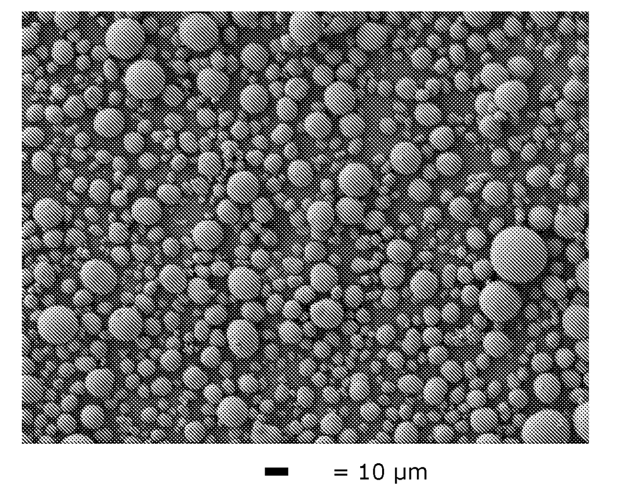
[0064]The same precipitation conditions as in Comparative Example 1 are used, but with seeding. For preparing the seed slurry, the seeds are re-dispersed into water to form a homogeneous slurry under stirring with a 200 g / L solid load level. The seeds are prepared by bead milling the big carbonate particles which are produced from the carbonate process without seeding of Comp. Ex. 1 (and hence M=M′), to decrease the median particle size (D50) to 1.0 μm.

[0065]The feed, carbonate solution and the seed slurry are pumped into the 10 L CSTR reactor. The molar ratio of CO3: Metal=1.0 and the molar ratio of M′seeds / M″feed is set at 0.005 (0.5 wt %), 0.01 (1.0 wt %) and 0.02 (2.0 wt %) consecutively, and the residence time is set at 3 hours. The feed solution, carbonate solution and seed slurry are continuously pumped into the CSTR reactor set at a precipitation temperature of 90° C., with an impeller stirring speed at 1000 rpm. The carbonate precursor slurry is collected through the overfl...

example 2

[0069]The same precipitation conditions as in Comparative Example 2 are used, but with seeding. Small seed particles (1.0 μm) are produced by ball milling the big carbonate precursor particles collected under the same precipitation conditions without seeding from a CSTR reactor (Comp. Ex. 2, hence M=M′). For preparing the seed slurry, small size MCO3 particles (Ni:Mn:Co=22:67:11) are re-dispersed into water to form a homogeneous slurry under stirring with a 150 g / L solid loading level.

[0070]The feed, hydroxide and carbonate solution, and the seed slurry are pumped into the 10 L CSTR reactor, with flow rates of Rfeed=25.7 ml / min, RNaOH=0.2 ml / min and Rcarbonate=29.7 ml / min, respectively. The molar ratio of CO3: Metal=1.0, the molar ratio of OH:CO3=0.04, and the molar ratio of M′seeds / M″feed is set at 0.01 (1 wt %) and 0.05 (5 wt %) consecutively. The residence time is set at 3 hours. The solutions are continuously pumped into the CSTR reactor at a precipitation temperature of 80° C.,...

example 3

[0074]Preparation of feed solution: NiSO4, MnSO4, CoSO4 are dissolved in deionized water and a transition metal solution is prepared, with a concentration of Ni, Mn, Co of 1.2 mol / L, 0.4 mol / L, 0.4 mol / L, respectively (Ni:Mn:Co=60:20:20). For preparing the carbonate solution Na2CO3 is dissolved in deionized water and a 1.65 mol / L Na2CO3 solution is obtained.

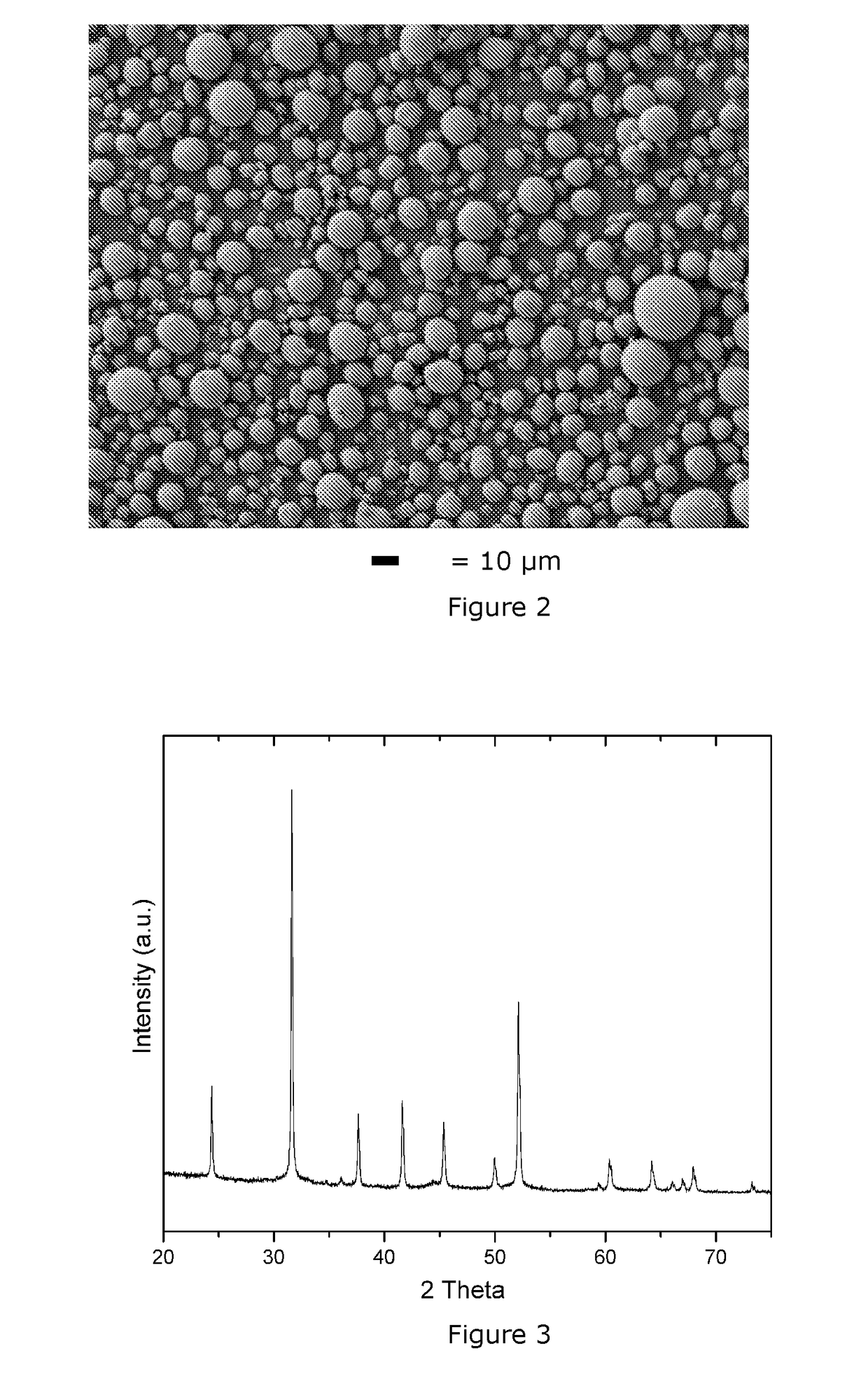
[0075]The same precipitation conditions as in Example 1 are used, but with M′seeds / M″feed=0.04 and MnCO3 seeding (here Mn=M′≠M). The MnCO3 seeds are produced by ball milling commercially available MnCO3 product to 0.5 μm and then dispersing it into water. The solid loading of the seeds slurry is 100 g / L. Before seeding, the particle size of the carbonate precursor in the reactor is continuously fluctuating and the D50 is 24.8 μm. After seeding, the median particle size in the reactor is stabilized at 7.1 μm. The carbonate precursor slurry is collected through the overflow of the CSTR reactor. Then, the obtained precursor slurry i...


PUM

PropertyMeasurementUnit
median particle size D50aaaaaaaaaa
concentrationaaaaaaaaaa

Abstract

A method for producing a M-carbonate precursor of a Li-M oxide cathode material in a continuous reactor, wherein M=NixMnyCozAn, A being a dopant, with x>0, y>0, 0≦z≦0.35, 0≦n≦0.02 and x+y+z+n=1, the method comprising the steps of: —providing a feed solution comprising Ni-, Mn-, Co- and A-ions, and having a molar metal content M″ feed, —providing an ionic solution comprising either one or both of a carbonate and a bicarbonate solution, the ionic solution further comprising either one or both of Na- and K-ions, —providing a slurry comprising seeds comprising M′-ions and having a molar metal content M′ seeds, wherein M′=Nix′Mny′Coz′A′n′, A′ being a dopant, with 0≦x′≦1, 0≦y′≦1, 0≦z′≦1, 0≦n′≦1 and x′+y′+z′+n′=1, and wherein the molar ratio M′ seeds/M″ feed is between 0.001 and 0.1, —mixing the feed solution, the ionic solution and the slurry in the reactor, thereby obtaining a reactive liquid mixture, —precipitating a carbonate onto the seeds in the reactive liquid mixture, thereby obtaining a reacted liquid mixture and the M-carbonate precursor, and —separating the M-carbonate precursor from the reacted liquid mixture.

Description

TECHNICAL FIELD AND BACKGROUND[0001]The invention relates to a carbonate precursor material for a lithium nickel manganese cobalt oxide, to be used as a cathode material for Li-ion batteries, and a method for producing the carbonate precursor.[0002]In present and future applications, Li batteries with high energy density are needed. A high energy density can be achieved by cathodes having either one or (preferably) both of a high volumetric density and a high specific reversible discharge capacity. For a long time, LiCoO2 (or “LCO”) was the dominating cathode material for rechargeable lithium batteries. LCO has a relatively high capacity (150-160 mAh / g when cycled at 3-4.3V) together with a high density (the true density is about 5.05 g / cm3) and is relatively easy to produce. It has a relatively high Li diffusion, so it is possibly to utilize large and dense particles (10-20 μm size) with a small surface area (0.1-0.5 m2 / g). All in all, commercial LCO is a robust and easy to manufac...

Claims


Application Information

Patent Timeline
Patent Type & Authority Applications(United States)
IPC IPC(8): H01M4/1391H01M4/04H01M4/505H01M10/052H01M4/525
CPCH01M4/1391H01M10/052H01M4/0471C01P2006/12H01M4/505C01P2002/52C01P2004/51H01M4/525H01M4/485C01G53/006C01G53/44C01P2002/54C01P2002/72C01P2004/32C01P2004/61C01P2006/11C01P2006/40Y02E60/10C01G53/06Y02T10/70
Inventor HU, JINHONG, HEONPYOPAULSEN, JENSOH, JINDOONELIS, DANIELROBERT, ERIC
Owner UMICORE AG & CO KG
Why Eureka
Try Eureka