
Application method and device for cold field plasma discharge assisted high energy ball milled powder

a plasma discharge and high-energy ball milling technology, applied in the field of mechanical manufacture and powder metallurgy technology, can solve the problems of large energy consumption, difficult introduction of plasma into the high-energy ball milling device, low efficiency and other shortcomings, etc., and achieve the effects of improving the processing efficiency and the effect of the ball mill, avoiding the burning of the ball milling system, and strong destructive power

Active Publication Date: 2017-12-07
SOUTH CHINA UNIV OF TECH
View PDF5 Cites 7 Cited by
  • Summary
  • Abstract
  • Description
  • Claims
  • Application Information

AI Technical Summary

Benefits of technology

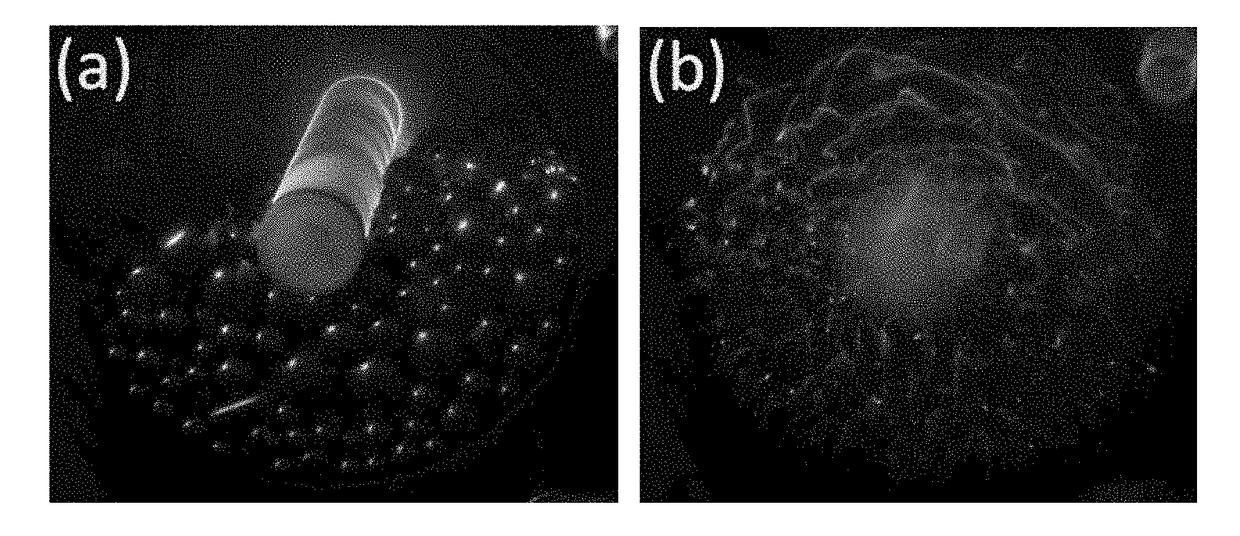
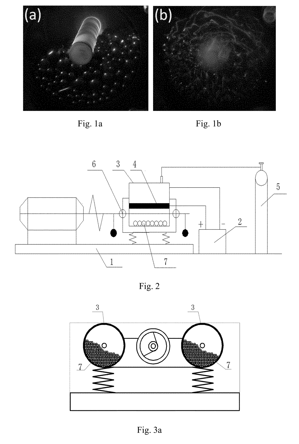
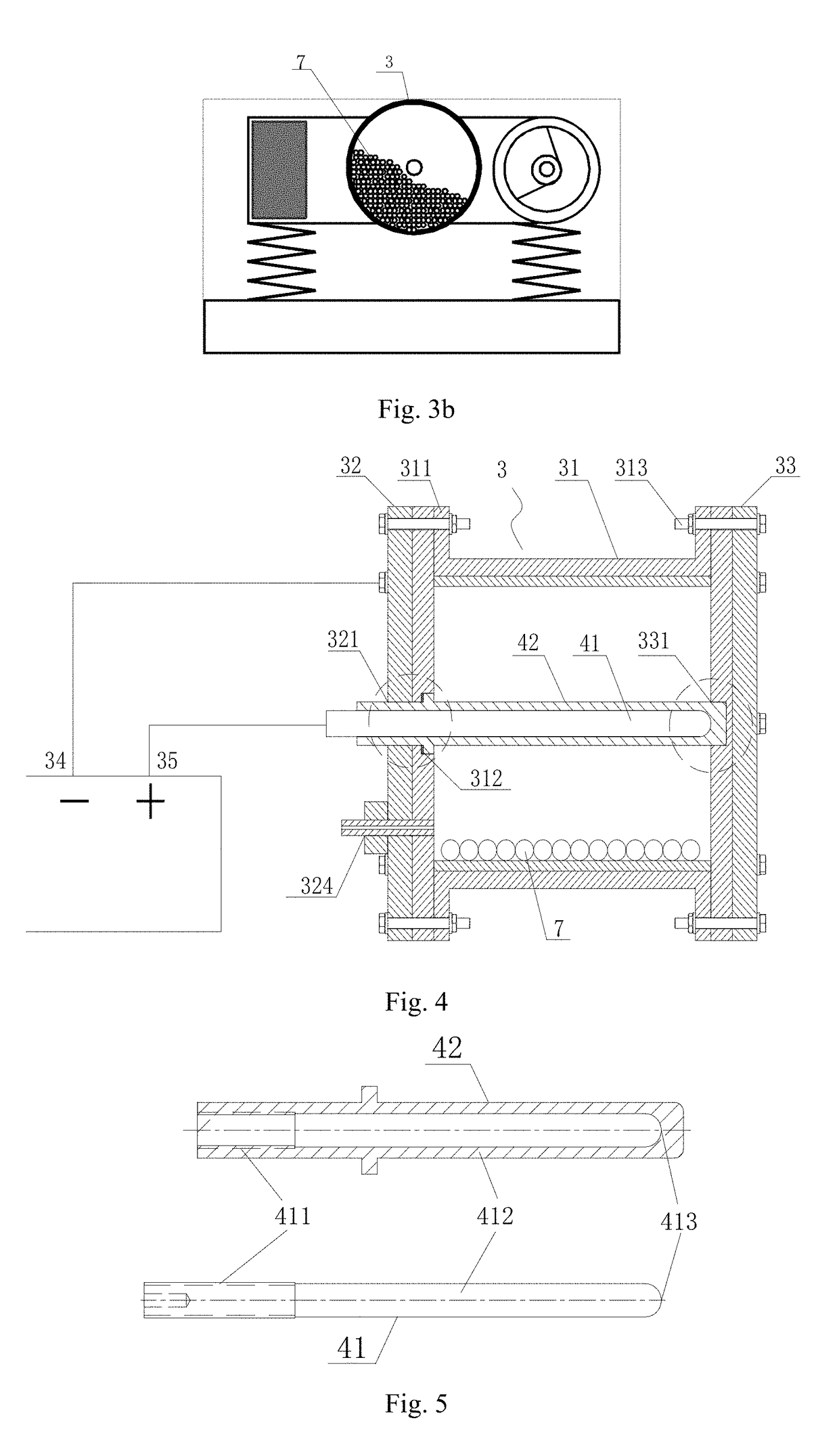
The present invention is a method for improving the mechanical alloying efficiency of materials using high energy ball milling assisted by plasma generated through a dielectric barrier discharge. The controllable atmosphere system mounted above the inlet and outlet holes of the discharge ball milling tank can independently regulate the ball milling effects of plasma on the processed powder under different atmospheric pressure and in various atmospheres of argon, nitrogen, ammonia, hydrogen and oxygen. The method utilizes a unique discharge form with a large number of fine fast pulse discharge channels generated by dielectric barrier discharge. The dielectric barrier discharge is introduced into the high-speed vibrating ball milling tank through a solid insulation medium on the outer layer of the electrode bar, which can simultaneously bear high-voltage discharge and mechanical shock failure of the grinding ball. The discharge space pressure is set to a non-thermal equilibrium discharge state with a pressure of about 102 to 106 Pa and discharge plasmas are introduced to input another kind of effective energy to the processed powder, accelerating the refinement process and the alloying process under the combined action of the mechanical stress effect and the external discharge plasma. The use of dielectric barrier discharge plasma as a plasma source ensures that the plasma is not a thermal plasma and avoids burning of the ball milling system, while the high-speed vibrating ball milling device can uniformly process the powder and improve the processing efficiency and the effect of the ball mill.

Problems solved by technology

However, the current mechanical alloying application is mainly concentrated in the planetary and agitating ball mills, having large energy consumption, low efficiency and other shortcomings.
However, plasma is seldom used for processing powder particles, and especially the introduction of plasma into the high energy ball milling device is more difficult, which is mainly due to the following two aspects: first, due to the accumulation of powder and the agglomeration among particles, the surface of the particles without exposure to the plasma atmosphere cannot be processed, and it is difficult to get all the particles processed, resulting in incomplete and nonuniform particle processing and a poor processing effect; second, the discharge electrode is seriously damaged under the combined action of the high-speed collision and the high-voltage discharge of the grinding ball in the high energy ball milling tank, thus having a very short life in the ball milling tank.
A patent CN 1718282 A, disclosing a plasma assisted high energy ball milling method, mainly introduced how to achieve and improve the plasma discharge assisted ball milling effect on the basis of an ordinary ball mill, but did not further disclose the specific structure of a main engine of the ball mill or the structure design of the discharge ball milling tank, in particular the material selection and design of the dielectric barrier discharge electrode bar.
In fact, the plasma assisted high energy ball mill has various technical problems with the external plasma power supply, the discharge ball milling tank, the dielectric barrier discharge electrode bar and the like, and especially has mutual fitting, local high intensity breakdown discharge, plasma discharging current strength control and other issues in the process of introducing the electrode bar into the ball milling tank, and the electrode bar itself is limited by the various problems affecting life that are caused by the material and structure, which are not resolved by the above invention patent.
Patents CN 101239334 A and CN 1011239336 A respectively disclosed a plasma assisted high energy roller ball milling device and a plasma assisted agitating ball milling device, which were primarily obtained by modification on the conventional roller and agitating ball mill; however, these two ball mills have small mechanical energy and low ball milling efficiency, not only difficult to regulate the ball milling energy in a wide range, but also unsuitable for the plasma assisted high efficient refining effect.
However, since the planetary ball mill has to achieve rotation and revolution of the ball milling tank, the electrode introduced into the ball milling tank is extremely unstable; in addition, the electrode bar installed in the ball milling tank has a serious hindrance to the collision of the grinding ball, which weakens the ball milling advantage of the planetary structure.
In the actual processing and assembly process, this fitting can never avoid the damage done by the residual air to the electrode bar in the discharge process, and thus the actual life of the electrode bar cannot be greatly improved.
However, these invention patents are limited to the field of the planetary ball mill, and do not involve the application of the external plasma electric field.

Method used


Image

  • Application method and device for cold field plasma discharge assisted high energy ball milled powder
  • Application method and device for cold field plasma discharge assisted high energy ball milled powder
  • Application method and device for cold field plasma discharge assisted high energy ball milled powder

Examples


example 1

[0086]Step 1: Using an electrode bar composed of an inner copper core and an outer polytetrafluoroethylene layer, wherein the tightening end threadedly fitted in insulation with the outer PTFE layer, the discharge end had a bare rod structure (instead of the thread structure), a heat-resistant adhesive was fully filled in the fitting gap between the electrode layer and the polytetrafluoroethylene layer to avoid the presence of air, and the top of the electrode had a spherical structure to fit in with the outer insulating dielectric layer. Mounting the electrode bar in a 4 L ball milling tank, putting the grinding ball and the powder to be processed into the ball milling tank, and mounting the dielectric barrier discharge electrode bar in the center of the ball milling tank to bring the electrode bar into contact with the grinding ball and the powder to be processed, and then sealing and fixing the ball milling tank with the end cap thereof; wherein the electrode bar had a diameter o...

example 2

[0090]Steps 1 and 2: Same as Example 1; and

[0091]Step 3: same as Example 1, except that the rotational speed of the ball mill was 960 rpm.

[0092]The results showed that the service life of the electrode bar could reach about 30 h.

example 3

[0093]Step 1: Same as Example 1, except that the ball milling volume was 0.15 L, the diameter of the electrode bar was 20 mm, and the grinding ball was made of stainless steel;

[0094]Step 2: same as Example 1; and

[0095]Step 3: same as Example 1, except that the discharge current was 1.0 A, and the rotational speed of the ball mill was 960 rpm.

[0096]The results showed that the service life of the electrode bar could reach about 35 h.


PUM

PropertyMeasurementUnit
Pressureaaaaaaaaaa
Electric potential / voltageaaaaaaaaaa
Frequencyaaaaaaaaaa

Abstract

The present invention provides an application method for cold field plasma discharge assisted high energy ball milled powder and a plasma assisted high energy ball milling device using the method for cold field plasma high energy ball milled powder. The present invention generates plasma by using dielectric barrier discharge and introducing a dielectric barrier discharge electrode bar into a high-speed vibrating ball milling tank, which requires that, on one hand, a solid insulation medium on the outer layer of the electrode bar can simultaneously bear high-voltage discharge and mechanical shock failure of the grinding ball, and on the other hand, the high-speed vibrating ball milling device can uniformly process the powder. Based on the ordinary ball milling technology, the discharge space pressure is set to a non-thermal equilibrium discharge state with a pressure of about 102 to 106 Pa, discharge plasmas are introduced to input another kind of effective energy to the processed powder, so as to accelerate refinement of the powder to be processed and promote the alloying process under the combined action of the mechanical stress effect and the thermal effect of the external electric field, thereby greatly improving the processing efficiency and the effect of the ball mill.

Description

FIELD OF THE INVENTION[0001]The present invention, belonging to the field of the mechanical manufacture and powder metallurgy technology, relates to a high energy ball milling device, in particular to a cold field plasma assisted high energy ball milling device and its application to preparation of cemented carbide, lithium ion batteries and hydrogen storage alloy powder materials.BACKGROUND OF THE INVENTION[0002]An ordinary high energy ball milling method for preparing alloy powder, as currently one of the most commonly used technologies for preparing and mechanically alloying nanomaterials and micron materials, generally refines the metal or alloy powder to a nanometer and micron scale by rotation or vibration with a high energy ball mill, that is, putting two or more kinds of powder at the same time into a ball milling tank of the high energy ball mill, and subjecting the powder particles to a repeated process of rolling, pressing, crushing and re-pressing (i.e., repeated cold we...

Claims


Application Information

Patent Timeline
IPC IPC(8): B02C19/18B22F9/14B02C17/18
CPCB02C19/18B02C17/18B22F9/14B02C17/14B02C17/1875B02C19/16
Inventor ZHU, MINZENG, MEIQINLU, ZHONGCHENOUYANG, LIUZHANGWANG, HUIHU, RENZONG
Owner SOUTH CHINA UNIV OF TECH
Learn More