This procedure has several disadvantages, including: (1) the discomfort associated with the procedure, which should be performed repeatedly each day; (2) the near impossibility of sufficiently frequent sampling (some blood glucose excursions require sampling every 20 minutes, or more frequently, to accurately treat); and (3) the requirement that the user initiate
blood collection, which precludes warning strategies that rely on automatic
early detection.
Using the extant fingersticking procedure, the frequent sampling
regimen that would be most medically beneficial cannot be realistically expected of even the most committed patients, and automatic sampling, which would be especially useful during periods of sleep, is not available.
Although this sensor provided direct recording of blood glucose, which is most advantageous for clinical applications, the described implantation at a central venous site poses several risks and drawbacks, including risk of blood
clot formation and
vascular wall damage.
Light-based systems using either absorption of light, or emission of light when glucose is “excited” by light have not proven to be accurate since there is no specific light absorption or
emission spectrum for glucose.
Furthermore, numerous other chemicals or interfering substances in the blood overlap in spectrum with glucose, causing optical methods to be insufficiently specific for glucose monitoring.
However, this requirement gives rise to a sensor design problem related to “
oxygen deficit,” since the concentration of
oxygen in bodily tissues is significantly less than that of glucose.
As the
chemical reaction, and thus, the sensor
signal, is limited by the reactant that is present in the sensor's
reaction zone at the lowest concentration, an implanted sensor of simple construction would remain limited by oxygen, and would therefore be insensitive to the
metabolite of interest (e.g. glucose).
However, one problem with the use of a macroporous or microporous membrane relates to
exposure of the sensing element of the sensor to the environment of the body, which can result in “
fouling” or other deleterious effects.
However, a major
disadvantage of vascular implantation is the possibility of eliciting blood clots or
vascular wall damage, as noted supra.
However, because the
long axis of the “pocket” is oriented parallel to the
electrode surface, this design may be less amenable to
miniaturization for tissue implantation, and may suffer from yet other disabilities relating thereto.
This substantially reduces the hydrophilic volume available for
enzyme inclusion sufficient to counter inactivation during long-term operation.
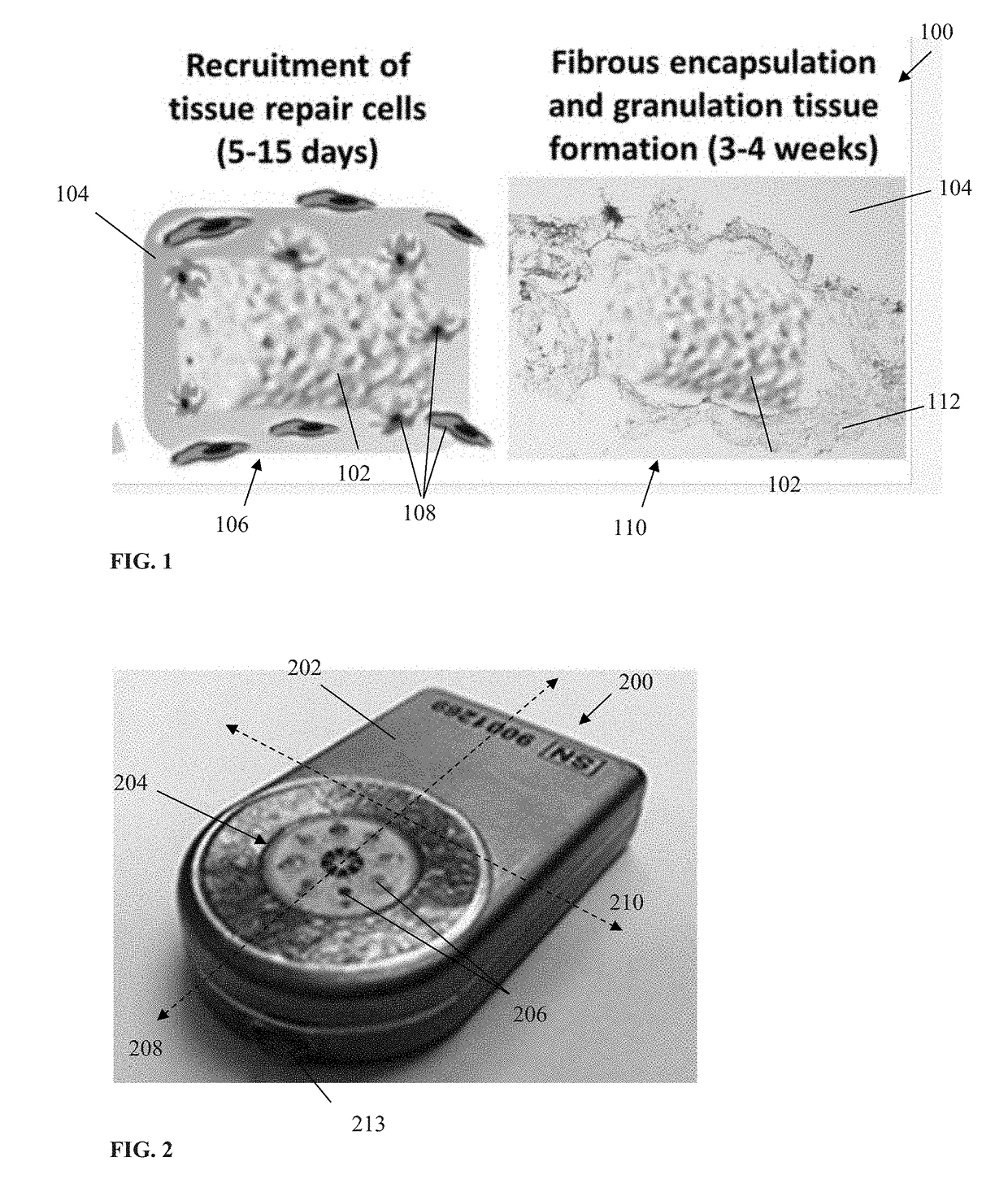
In some cases, although the living tissue adapts to the
implanted device, the
wound healing process may render the device non-functional (or at very least reduce its functionality and / or accuracy), thereby negating any benefit to the patient.
For example, in implanted devices that depend on diffusive transport of solutes to or from the bloodstream (e.g. implanted chemical sensors), such responses can negatively
impact device operation due to an increase in
mass transfer resistance between the bloodstream and active portions of the device surface resulting from an FBR-mediated development of
fibrous tissue surrounding the device.
The FBR also can complicate explants of the
implanted device (due to, e.g., the FBR causing significant encapsulation of the
implanted device, thereby increasing its
effective size when explanted), and result in yet other disabilities.
Such approaches have typically used materials for such layer(s) which are designed to encourage
blood vessel growth and
perfusion in the vicinity of the sensor or into the layer(s), which is undesirable, because such modulated responses are often not predictable and furthermore may not be sustainable for extended durations.
For instance, electrical currents and potentials associated with an electrolytic sensor can, if sufficiently
proximate to the host's tissue, induce varying degrees of the aforementioned tissue response, which is likewise undesired.
Prolonged chronic
inflammation is also associated with increased FBR and
fibrosis, and may lead to
implant rejection and require extraction or “explant” (i.e., removal of the sensor).
The explant process generally becomes more difficult and traumatic to the tissue if there is significant FBR and
fibrosis, which may cause tissue to responsively grow
connective tissue around the implanted sensor over time.
In some conventional implanted sensors, even normal degrees of FBR and
fibrosis may obstruct the sensing components, thereby rendering the device non-functional and necessitating replacement (i.e., explant of the current device and implant of a
new device), which may reinitiate the
wound healing process.
Such approaches have typically used materials for such layer(s) which are designed to encourage
blood vessel growth and
perfusion in the vicinity of the sensor or into the layer(s), which is undesirable, because such modulated responses are often not predictable and furthermore may not be sustainable for extended durations.
The response and accuracy of conventional sensors can be adversely affected by FBR or other tissue response in the region of the
analyte sensor as noted above; this effect can be exacerbated the longer the sensor is left implanted.
Specifically, as the FBR or tissue response proceeds over time, the mechanical relationship between an implanted sensor device and the host's tissue in the immediate area of implantation (including micro-
perfusion within blood vessels adjacent to the sensor) can significantly change due to movement between the tissue (and the microvascular structures therein which provide communication between the device and the body's
circulatory system) and the device surface, thereby potentially degrading the accuracy and / or reliability of the sensor device.
Hence, there is somewhat of a “catch-22” involved; any effective sensor will need to be implanted at
a site with sufficient available blood glucose (delivered via blood vessels or microvasculature of the host in that area) and maintain close physical contact with the tissue at that site for proper and accurate sensor operation, yet such
close contact (including even the act of implantation) can trigger a tissue response which can be deleterious to the accuracy and operation of the sensor.
Sensors relying on the
diffusion of glucose are particularly susceptible to variations in tissue response and encapsulation, since these factors directly affect the rate and magnitude of glucose
diffusion from the capillaries to the implanted sensor element.
Lastly, many conventional implantable devices are sufficient only for relatively short-term implantation due to expiration or exhaustion of one or more components of the device (as well as the aforementioned degradation of accuracy / response due to effects of the FBR).

