
Immobilization of cells or virus particles on protein structures using a microfluidic chamber

a technology of cell or virus particles and protein structures, which is applied in the field of immobilization of cells or virus particles on protein structures using a microfluidic chamber, can solve the problems of inability to reliably detect single cells, high demand, and inability to allow single cell analysis, and achieves high specificity, high binding efficiency, and high recovery.

Inactive Publication Date: 2018-01-25
KARLSRUHER INST FUR TECH +1
View PDF5 Cites 1 Cited by
  • Summary
  • Abstract
  • Description
  • Claims
  • Application Information

AI Technical Summary

Benefits of technology

The technical problem addressed by this patent is how to effectively immobilize, identify, and isolate cells or virus particles of interest from biological fluids, even when they are present in low numbers on a background of high numbers of other cells or virus particles. The method should have a high binding efficiency, specificity, and recovery, and should allow for easy access to immobilized cells for further analysis.

Problems solved by technology

The identification and hence enrichment and localization of cells of interest, such as CTCs, but also other cells including bacterial cells, or virus particles of interest in biological fluids is still a challenge, even after decades of research.
However, recent studies have shown that EpCAM is not always a reliable marker.
On this account, the development of CTC-capturing devices that can easily target different surface epitomes besides EpCAM, are able to handle high blood volumes and allow single cell analysis is still challenging, but highly demanded.
Further, said methods often achieve only inadequate binding efficiency, specificity and recovery of cells.

Method used


Image

  • Immobilization of cells or virus particles on protein structures using a microfluidic chamber
  • Immobilization of cells or virus particles on protein structures using a microfluidic chamber
  • Immobilization of cells or virus particles on protein structures using a microfluidic chamber

Examples


example 1

[0092]Design of a Microfluidic Chip and an Integrated Microarray

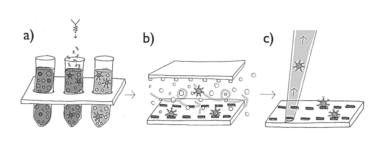
[0093]The capturing strategy presented here is based on a functional dot pattern combined with a microfluidic chaotic mixing system. A standard microscopy slide is coated with bovine serum albumin (BSA) to create both a passive and integrative interface: passive, as BSA prevents proteins and cells from unspecific binding; integrative, as fluorescein can bind covalently to BSA molecules induced by photobleaching. The latter is exploited to generate a chemisorbed dot pattern on the microscopy slide that is stable under streaming liquid condition. Lithography is carried out by polymer pen lithography (PPL), a high throughput technique with full pattern flexibility. FIG. 12A presents a schematic of the PPL process: a two dimensional array of polydimethylsiloxane (PDMS) pyramids is brought in contact with a piece of silicon coated with biotin-4-fluorescein acting as an ink pad. Capillary forces cause a wetting of the pens th...

example 2

[0095]Identification and Single Cell Extraction

[0096]Capture approaches based on microfluidic chips aim primarily at CTC quantification, however, immunocytochemistry and fluorescence in situ hybridization (FISH) can be conducted on captured cells inside these closed systems. Due to the three-dimensional inner architecture that is homogeneously coated with functional molecules captured CTCs cannot be extracted and individually investigated any further. Immobilizing CTCs on a plane surface has some advantages if further investigation needs to be performed. The approach taken in the present invention immobilizes cells exclusively on the functional micropattern; other surfaces like the herringbone-structured ceiling and the channel walls are passivated with BSA preventing cells to bind there. Having the captured CTCs on a flat surface allows picking single cells by a micromanipulator. FIG. 16A shows an overlay of fluorescence and brightfield micrographs that illustrates the picking proc...

example 3

[0099]Performance

[0100]The low quantity of CTCs in blood is a challenge for all capturing strategies. A relatively large blood volume of several mL needs to be processed to isolate usually some hundred CTCs. When facilitating specific surface proteins as CTC marker, all blood cells need to be brought in contact with an interacting surface. The first experiments to proof the stability and binding dynamics of the micropatterns have been performed with 100 μL cell suspension on cover slips. EpCAM micropatterns have been created by direct protein deposition and it was tried to incubate biotinylated EpCAM on a streptavidin array. However, both approaches did not show sufficient binding results during a short-term incubation of 15 minutes. By sensitizing targeting cells with biotinylated EpCAM one can take advantage of the strong affinity between streptavidin and biotin. Live-imaging experiments show that 80% of biotinylated cells are trapped on a streptavidin dot immediately after touchi...


PUM

PropertyMeasurementUnit
temperatureaaaaaaaaaa
side lengthaaaaaaaaaa

Abstract

The present invention relates to methods for the immobilization of cells or virus particles of interest expressing one or more predetermined surface marker(s) on defined spots on a solid support, comprising the steps of providing a biological fluid sample suspected of containing cells or virus particles of interest; labeling the cells or virus particles of interest with antibodies, antibody fragments or antibody mimetics directed against the one or more predetermined surface marker(s) and carrying a first binding agent; and contacting the labeled cells or virus particles of interest with a solid support (biochip), said solid support comprising an array of defined isolated spots of a solid support-bound second binding agent, wherein the first and second binding agents can bind to each other. The present invention further relates to devices for the isolation of cells or virus particles of interest expressing one or more predetermined surface marker(s).

Description

CROSS-REFERENCE TO RELATED APPLICATIONS[0001]This application is a U.S. National Phase patent application of International Application Serial Number PCT / EP2016 / 000191, filed on Feb. 5, 2016, which is hereby incorporated by reference in its entirety, and which claims the benefit of European Patent Application Number 15000479.4, filed on Feb. 13, 2015, which is hereby incorporated by reference in its entirety.BACKGROUND OF THE DISCLOSURE[0002]The present invention relates to methods for the immobilization of cells or virus particles of interest expressing one or more predetermined surface marker(s) on defined spots on a solid support, comprising the steps of providing a biological fluid sample suspected of containing cells or virus particles of interest; labeling the cells or virus particles of interest with antibodies, antibody fragments or antibody mimetics directed against the one or more predetermined surface marker(s) and carrying a first binding agent; and contacting the labeled...

Claims


Application Information

Patent Timeline
Patent Type & Authority Applications(United States)
IPC IPC(8): G01N33/574B01L3/00
CPCG01N33/57492B01L3/502761B01L3/50273G01N2333/705B01L2400/0406B01L2300/0819B01L2300/18C12N7/02G01N33/56966G01N33/56983G01N2469/10
Inventor HIRTZ, MICHAELFUCHS, HARALDPANTEL, KLAUSBRINKMANN, FALKO
Owner KARLSRUHER INST FUR TECH
Learn More