

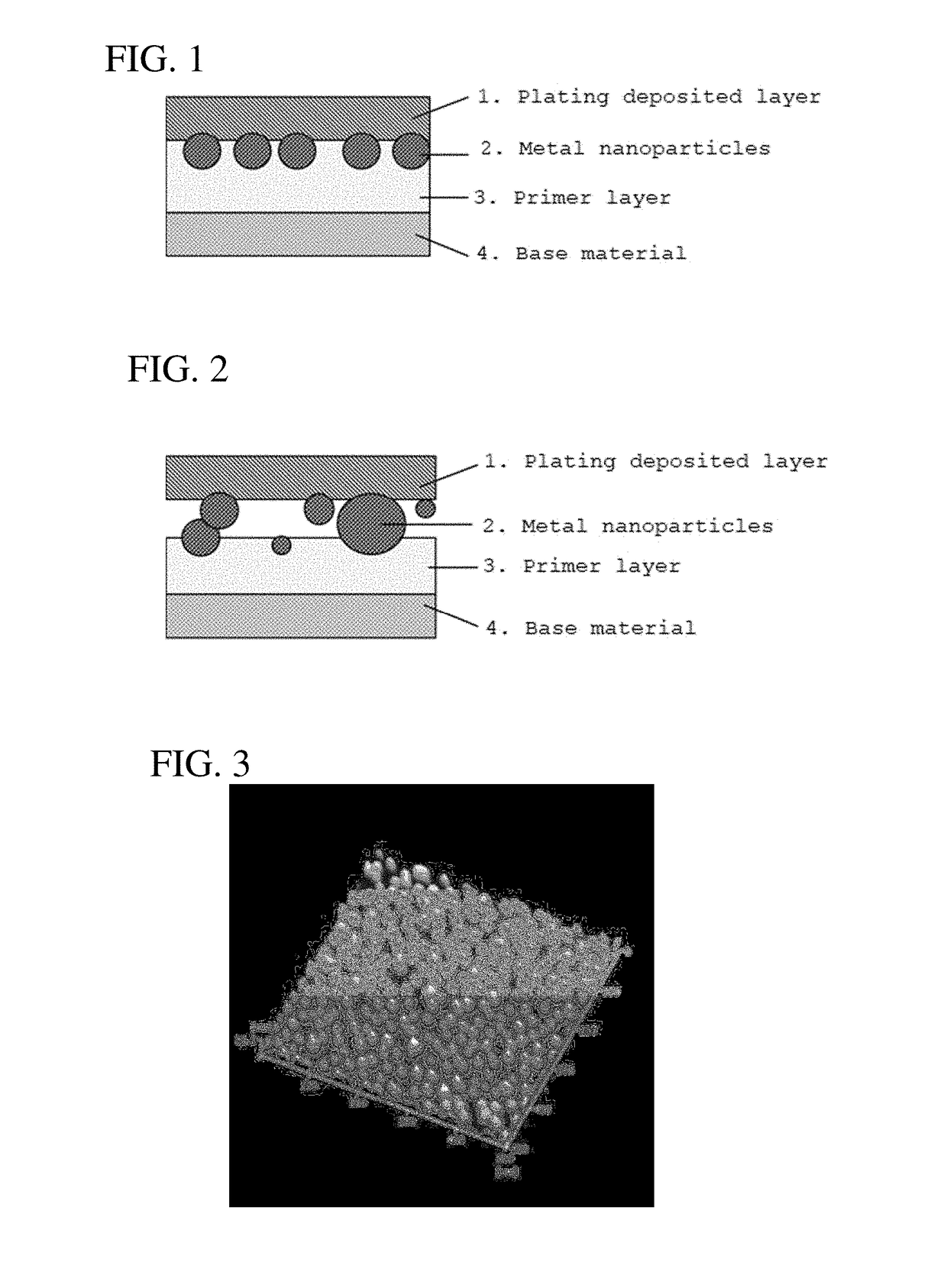
Laminate structure of metal coating
a metal coating and laminate technology, applied in the direction of superimposed coating process, liquid/solution decomposition chemical coating, insulating substrate metal adhesion improvement, etc., can solve the problems of insufficient adhesion power with plating deposited layer, limited surface form of primer material used, and inconvenient use of conventional methods. achieve stable joint strength, improve adhesion power, and dramatically improve the laminate structure of metal coating
- Summary
- Abstract
- Description
- Claims
- Application Information
AI Technical Summary
Benefits of technology
Problems solved by technology
Method used
Image

Examples
example 1
[0056]As an insulating base material A, glass (EAGLE XG manufactured by CORNING) was used. As a primer solution, a polyester resin solution (glass transition temperature (actual measurement value) 72° C.) was used. The primer solution was applied to the insulating base material A by a bar coating method and dried at 100° C. for 5 minutes to forma primer layer with a thickness of 0.12 μm2 as a dried coating thickness.
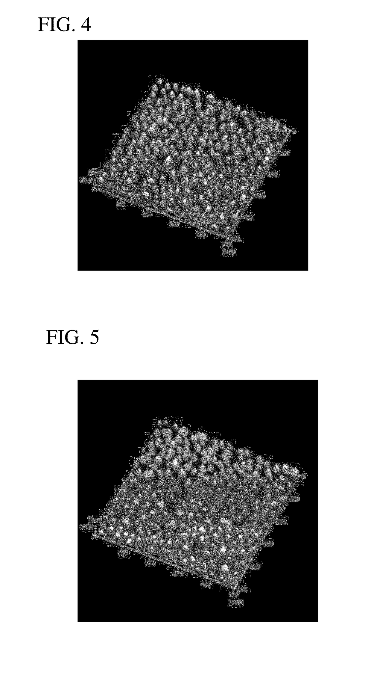
[0057]This insulating base material A provided with the primer layer was immersed in an aqueous solution containing colloidally dispersed spherical gold (Au) nanoparticles (0.1 g / L as Au) with an average particle diameter of 20 nm (variation coefficient C.V.=0.15) for 10 minutes and then washed with pure water. As a result, a substrate having a catalyst layer in which nanoparticles with an average particle diameter of 20 nm are adsorbed on the primer layer at an average adsorption density of 273 particles / 0.25 μm2 was obtained (FIG. 3). A scanning probe microscope (AFM54...
example 2
[0063]As an insulating base material B, a polyester film (Lumirror S10 manufactured by Toray Industries, Inc.) was used. As a primer solution, an amino group-containing polyester resin solution (glass transition temperature 80° C.) was used. The primer solution was applied to the insulating base material B by a bar coating method and dried at 100° C. for 5 minutes to form a primer layer with a thickness of 0.07 μm as a dried coating thickness.
[0064]Next, this base material was irradiated with a wavelength of 300 nm or less for 30 seconds from a distance of 10 mm by a UV light source device (Model 312 manufactured by TECHNOVISION, Inc.) A quartz mask having a light shielding pattern formed with chromium was put between the light source and the base material. As a result, an amino group on the primer at a site to which ultraviolet rays were applied disappeared.
[0065]The insulating base material B thus treated was immersed in an aqueous solution (zeta potential −56 mV) containing collo...
example 3
[0068]As an insulating base material C, a polyimide film (UPILEX 50SGA manufactured by Ube Industries, Ltd.) was used. As a primer solution, an olefin resin solution (glass transition temperature 130° C.) was used. The primer solution was applied to the insulating base material C by a spin coating method and dried at 150° C. for 15 minutes to form a primer layer with a thickness of 0.3 μm as a dried coating thickness.
[0069]This insulating base material C provided with the primer layer was immersed in an aqueous solution containing colloidally dispersed spherical palladium (Pd) nanoparticles (0.3 g / L as Pd) with an average particle diameter of 3 nm (variation coefficient C.V.=0.40) and 0.01 g / L polyethylene imine (average molecular weight 10000) for 10 minutes to obtain a substrate provided with a catalyst layer having palladium (Pd) nanoparticles adsorbed on the primer layer.
[0070]Next, this substrate was immersed in a 52° C. electroless palladium (Pd) plating solution (LECTROLESS P...
PUM
| Property | Measurement | Unit |
|---|---|---|
| Tg | aaaaa | aaaaa |
| particle diameter | aaaaa | aaaaa |
| Tg | aaaaa | aaaaa |
Abstract
Description
Claims
Application Information