Co-extruded one-time-formed solar cell module backboard in three-layer structure

a solar cell module and backboard technology, applied in the field of one-time-formed solar cell module backboard in a three-layer structure, can solve the problems of poor heat conduction efficiency and heat resistance, low rate, and affect the power generation efficiency of the cell, and achieve high water resistance radio, good long-term ageing resistance, and high reflective rate

Active Publication Date: 2019-06-13
CYBRID TECHNOLOGIES INC
View PDF6 Cites 3 Cited by
  • Summary
  • Abstract
  • Description
  • Claims
  • Application Information

AI Technical Summary

Benefits of technology

[0004]For overcoming the defects of the prior art, the present invention aims to provide a solar cell module backboard in a three-layer structure, which has high water resistance radio, high reflective rate, good long-term ageing resistance and good environmental protection performance. The backboard consists of three films: a middle layer which is located in the middle as well as an outer layer and an inner layer which are located at the two sides of the middle layer by using a dynamic crosslinking extrusion technology which is also called a reactive crosslinking extrusion technology. The solar cell module backboard (4) is formed at one time by co-extruding three films and functional fillers by the reactive crosslinking extrusion technology and has high water resisting ability, high reflective rate, good long-term aging resistance performance of hydrolysis resistance, UV resistance and heat resistance, good dimensional thermal stability and good recoverability and environmental protection performance. The solar cell module backboard is in the three-layer structure comprising a core base layer made of a crosslinked polymer alloy film, the outer layer which is located at one side of an atmospheric surface thereof and consists of a co-extruded crosslinked polymer alloy layer and the inner layer which is located at the other side thereof, i.e., the side of a cell piece and consists of co-extruded crosslinked polymer alloy. Compared with the prior art, the backboard has better water resisting ability, higher reflective rate, better long-term aging resistance performances of hydrolysis resistance, UV resistance and heat resistance, better dimensional thermal stability, better recoverability and environmental protection performance and lower cost. Compared with a backboard in a co-extruded structure in the prior art, the backboard of the present invention has better heat resistance, better dimensional stability and higher mechanical breaking strength.
[0005]In the present invention, low-cost polyolefin polymer resins, reactive functional groups grafted by a grafting technology and polymer resins with reactive groups capable of reacting with the grafted functional groups are blended to carry out a crosslinking reaction in an extrusion process, thereby realizing a crosslinked network, improving heat resistance, enhancing mechanical strength and improving dimensional stability, meanwhile, the present invention uses the polymer resins with the reactive groups in each of the three layers as compatilizer, thereby enhancing the binding force between every two adjacent layers. Meanwhile, the crosslinked network is used for improving the hardness and the capabilities of friction resistance, scratching resistance, acid and alkali resistance, solvent resistance, ammonia resistance and salt spray resistance of the outer layer on the surface.
[0008]Namely a dense molecular network is formed through crosslinking of polymers inside each of the layers and between every two adjacent layers in a co-extrusion process, so as to achieve the purposes of improving heat resistance, heat stability and mechanical strength and enhancing the binding force between the middle layer 3 and the outer layer 1 and between the middle layer 3 and the inner layer 2, wherein the outer layer 1 and the inner layer 2 are located at the two sides of the middle layer 3. Meanwhile, the compatilizer compatible with the outer layer 1 and the inner layer 2 and added in the middle layer 3 is used, thereby achieving the purposes of enhancing the binding force between the middle layer 3 and the outer layer 1 and between the middle layer 3 and the inner layer 2, wherein the outer layer 1 and the inner layer 2 are located, at the two sides of the middle layer 3.
[0014]the functional fillers are used for enhancing reflective performance, heat dispersion, flame retardant property and color decoration performance, and the inorganic fillers are selected from one or a mixture of at least two of TiO2, Al2O3, aluminium hydroxide, talcum powder, SiO2, CaCO3, carbon black, mica powder, barium sulfate, diatomaceous earth, pumice powder and diamond powder; and
[0020]the functional fillers are used for enhancing reflective performance, heat dispersion, flame retardant property and color decoration performance, and the inorganic fillers are selected from one or a mixture of at least two of TiO2, Al2O3, aluminium, hydroxide, talcum powder, SiO2, CaCO3, carbon black, mica powder, barium sulfate, diatomaceous earth, pumice powder and diamond powder; and
[0026]the functional fillers are used for enhancing reflective performance, heat dispersion, flame retardant property and color decoration performance, and she inorganic fillers are selected from one or a mixture of at least two of TiO2, Al2O3, aluminium hydroxide, talcum powder, SiO2, CaCO3, carbon black, mica powder, barium sulfate, diatomaceous earth, pumice powder and diamond powder; and

Problems solved by technology

The backboard has the following defects that: the backboard is thicker, so that the heat conduction efficiency and the heat resistance are poorer; the reflective rate is low, so the power generation efficiency of the cell is affected; the UV resistance is low, so the material of the surface layer of the cell piece is pulverized too early, yellows, cracks, ages and fails; the water vapor permeation raise is high, so a Potential Induced Degradation (PID) phenomenon is caused; and snail trails are induced, so the power generation efficiency is reduced; the repair for the module is difficult; and the backboard is expensive.

Method used


Image

  • Co-extruded one-time-formed solar cell module backboard in three-layer structure
  • Co-extruded one-time-formed solar cell module backboard in three-layer structure
  • Co-extruded one-time-formed solar cell module backboard in three-layer structure

Examples


embodiment 1

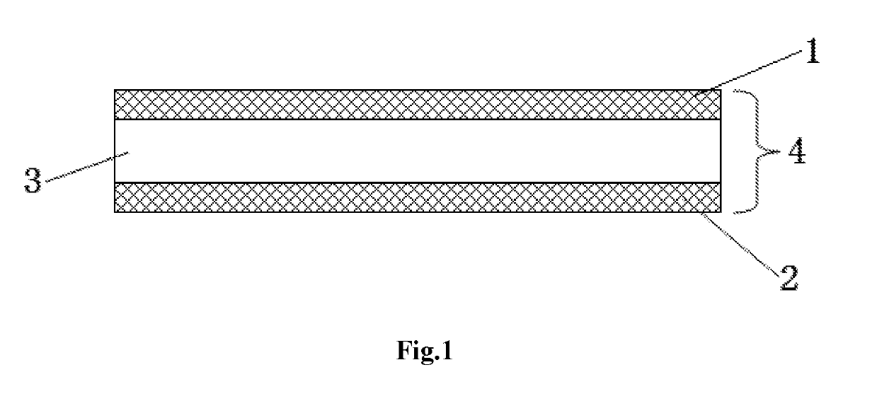
[0031]FIG. 1 is a structural schematic diagram of a solar cell module backboard 4 in a three-layer structure. The solar cell module backboard 4 comprises a middle layer 3 which is located in the middle as well as an outer layer 1 and an outer layer 2 which are located at the two sides of the middle layer; and is made by three-layer co-extrusion one-time continuous production, namely, hybrid polymer films are formed by a high-temperature co-extrusion film making process,

[0032]wherein the outer layer 1 comprises raw materials (by mass percent, similarly hereinafter) of 88% of PA12 and 12% of TiO2 and is 0.050 mm in thickness;

[0033]the chemical formula of the outer layer 1 is: [NH—(CH2)11—CO]n; the inner layer 2 comprises raw materials of 19% of EVA, 69% of LLDPE and 12% of TiO2 and is 0.050 mm in thickness;

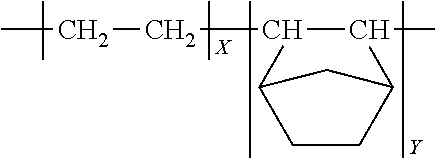
[0034]the chemical formula of the inner layer 2 is: (C2H4)x(C4H6O2)+(C2H4)n,

[0035]wherein the chemical formula of EVA is: (C2H4)x(C4H6O2)y, and the chemical formula of LLDPE is: (C2...

embodiment 2

[0039]FIG. 1 is a structural schematic diagram of a solar cell module backboard 4 in a three-layer structure. The solar cell module backboard 4 comprises a middle layer 3 which is located in the middle as well as an outer layer 1 and an outer layer 2 which are located at the two sides of the middle layer,

[0040]wherein the outer layer 1 comprises raw materials of 88% of PA12 and 12% of TiO2 and is 0.050 mm in thickness;

[0041]the chemical formula of PA12 is: [NH—(CH2)11—CO]n;

[0042]the inner layer 2 comprises raw materials of 88% of PA12 and 12% of TiO2 and is 0.050 mm in thickness:

[0043]the middle layer 3 comprises raw materials of 98% of PA12 and 2% of TiO2 and is 0.250 mm in thickness;

[0044]Hybrid polymer films are formed by a high-temperature co-extrusion film making process.

embodiment 3

[0045]FIG. 1 is a structural schematic diagram of a solar cell module backboard 4 in a three-layer structure. The solar cell module backboard 4 comprises a middle layer 3 which is located in the middle as well as an outer layer 1 and an outer layer 2 which are located at the two sides of the middle layer, and is made by three-layer co-extrusion one-time continuous production,

[0046]wherein the outer layer 1 comprises raw materials of 65% of HDPE-g-GMA, 23% of PA12 and 12% of TiO2 and is 0.050 mm in thickness, and the chemical formula of HDPE is:

[—CH2—CH2—]n;

[0047]the inner layer 2 comprises raw materials of 65% of HDPE-g-GMA, 23% of PA12 and 12% of TiO2 and is 0.050 mm in thickness; and

[0048]the middle layer 3 composes raw materials of 58% of HOPE 20% of PP-g-GMA, 20% of PA12 and 2% of TiO2 and is 0.250 mm in thickness. A crosslinking reaction is carried out on a part of raw materials by a high-temperature co-extrusion film making process, so as to form hybrid polymer alloy films.

[00...


PUM

PropertyMeasurementUnit
thicknessaaaaaaaaaa
thicknessaaaaaaaaaa
weight ratioaaaaaaaaaa

Abstract

The present invention discloses a co-extruded one-time-formed solar cell module backboard in a three-layer structure. The backboard is formed by co-extruding three layers: a middle layer located in the middle as well as an outer layer and an inner layer located at two sides of the middle layer, and has high water resisting capability, high reflective rate, good long-term aging resistance performances of hydrolysis resistance, UV resistance and heat resistance and good recoverability and environmental protection performance. Compared with the prior art, the backboard has better water resisting ability, higher reflectivity, better long-term aging resistance performances of hydrolysis resistance, UV resistance and heat resistance, better recoverability and environmental protection performance and lower cost. Compared with a backboard in a co-extruded structure in the prior art, the backboard of the present invention has better heat resistance, better dimensional stability and higher mechanical breaking strength.

Description

TECHNICAL FIELD[0001]The present invention relates to a co-extruded one-time-formed solar cell module backboard in a three-layer structure.BACKGROUND OF THE INVENTION[0002]A solar ceil module is usually a laminated structure and mainly includes a glass layer, an Ethylene / Vinyl Acetate (EVA) encapsulation layer, a silicon cell piece, an EVA encapsulation layer and a solar cell module backboard that are sequentially arranged, wherein the silicon cell piece is sealed and wrapped by two layers of EVA adhesive films. The solar cell module backboard has a main function of electrical insulation, can improve the mechanical strength of the solar cell module and can prevent water vapor from permeating into a sealing layer to affect the service life and the power generation efficiency of the cell piece. Since the solar cell module backboard is arranged on the outermost side of the solar cell module, the backboard is required to have good environmental erosion resistance. Therefore, the manufac...

Claims


Application Information

Patent Timeline
Patent Type & Authority Applications(United States)
IPC IPC(8): H01L31/049B32B27/08B32B27/20B32B27/32B32B27/34B32B27/30H01L31/048
CPCH01L31/049Y10T428/24967B32B27/20B32B27/32B32B27/34B32B27/30B32B2457/12B32B2264/102B32B2307/206B32B2307/306B32B2307/714B32B2307/7265B32B2307/71H01L31/0481B32B2250/24B32B2250/03B32B27/08B32B3/12B32B27/06B32B27/18B32B2457/10B32B7/10B32B27/302B32B27/308B32B27/325B32B27/365B32B2307/406B32B2307/416B32B2307/54B32B2307/712B32B2307/7246B32B2307/732B32B2307/734Y02E10/50Y10T428/24942Y10T428/24
Inventor CHEN, HONGYEWANG, LEIWU, XIAOPINGKEIICHI, UNOHIROSHI, TAKABATAKE
Owner CYBRID TECHNOLOGIES INC
Why Eureka
Try Eureka