

Multi-atomic layered materials
a multi-atomic, layered technology, applied in the direction of silicon compounds, cell components, crystal growth process, etc., can solve the problems of reducing the active surface area, reducing the catalyst lifetime, inherent catalytic properties, etc., to enhance chemical reaction selectivity and conversion, reduce the susceptibility to sintering, and distorted structures and/or bonding characteristics
- Summary
- Abstract
- Description
- Claims
- Application Information
AI Technical Summary
Benefits of technology
Problems solved by technology
Method used
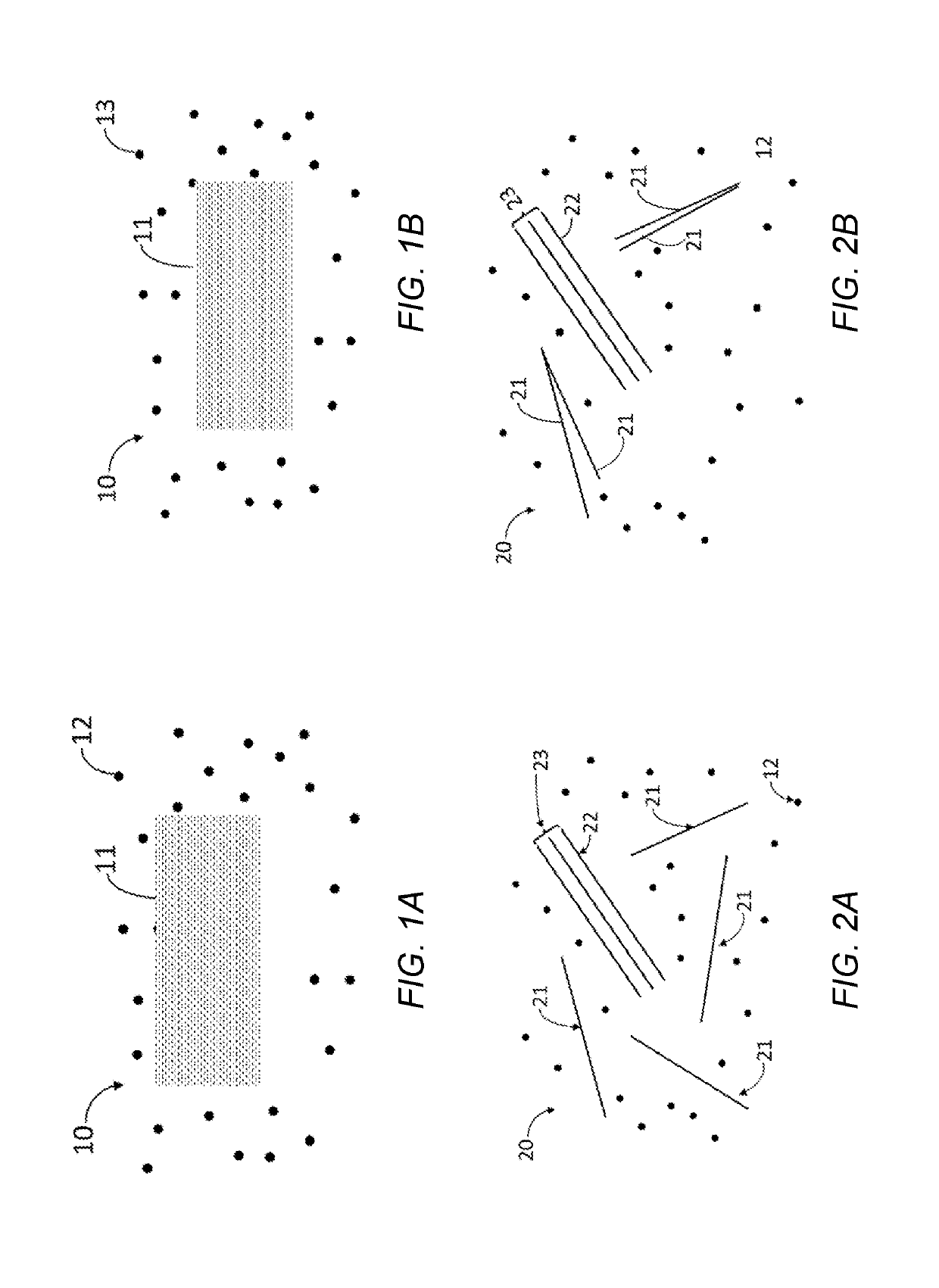
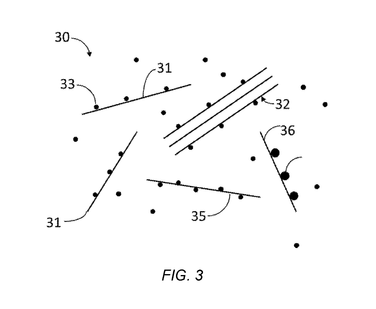
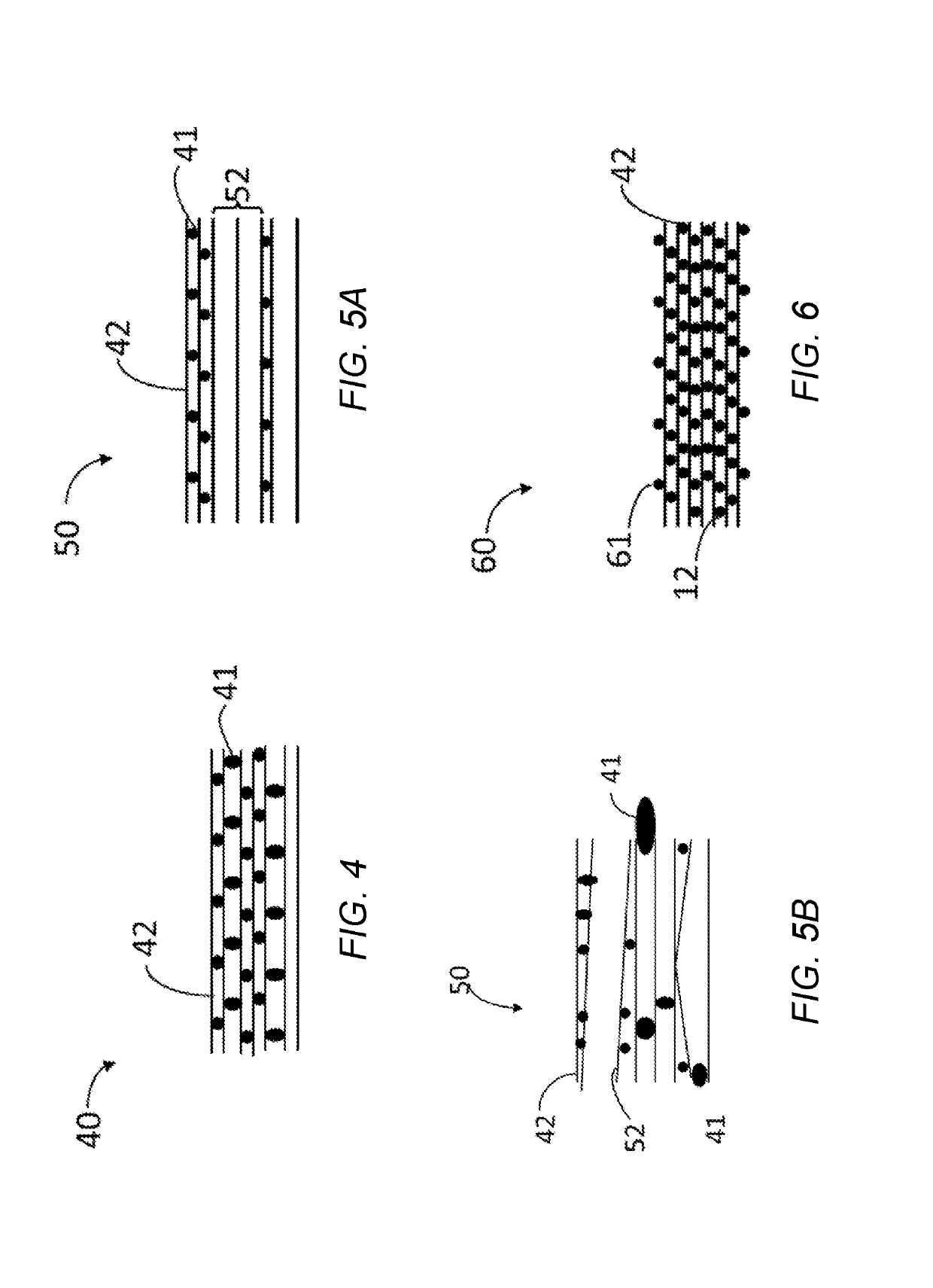
Image

Examples
example 1
Method of Making a Au Intercalated Silicene Multi-Atomic Layered Material of the Present Invention
[0089]In a controlled atmosphere (glove box), CaSi2 (1×10⁻³M) was added to KOH (20 ml, 0.01 M) solution and stirred for 1-3 hours. To a portion (2 mL) of the CaSi2 / KOH solution, isopropyl / hydrochloric acid (0.6 gm) was added and stirred from 5 to 60 min. During the addition and agitation, evolution of gas was observed. The gas was assumed to be H2. The acidified solution was sonicated for 15-30 min, and then HAuCl4 (2 ml of a 3-4 mg HAuCl4 in 40 ml water solution) was added under sonication. After 5-10 min of additional sonication, NaBH4 (1 ml of 4.5 mg NaBH4 in 2 ml water solution) was added, sonication was continued for 5-15 min, and then the solution was allowed to stand for >24 hrs for re-stacking of layered material to occur. The resulting solution had a top clear layer and precipitate. Characterization was conducted on the top clear solution layer and the precipitate. From the cha...
example 2
Characterization of Au Intercalated Silicene Multi-Atomic Layered Material of the Present Invention
[0090]Characterization of the reaction intermediates and products was performed using SEM, TEM, ICP, EDS, XRD and Raman methodologies.
[0091]After KOH Addition.
[0092]After KOH addition, SEM analysis was performed on the CaSi2. FIG. 9 is a SEM image of the bulk CaSi2 after KOH treatment. From the SEM, it was determined that the CaSi2 was not separated (i.e., in bulk form).
[0093]Immediately after Sonication has Ended.
[0094]The solution was sampled immediately after ending the sonication. FIG. 10 is a SEM image of the precipitated material immediately after ending the sonication. Comparing FIG. 10 to FIG. 9, it was determined that the bulk CaSi2 had separated and started to restack as silicene (2-D silicon) with gold intercalated in the layers as layers are present in FIG. 10. Gold intercalates are the light colored spots (as indicated by the arrow).
[0095]1 Day after Sonication.
[0096]FIG. ...
PUM
 Abstract
Description
Claims
Application Information