

Photocatalyst for efficient hydrogen generation
a photocatalyst and hydrogen generation technology, applied in the field of zscheme photocatalyst system, can solve the problems of cds based photocatalysts suffering from catalytic decay, the price of photovoltaic (pv) modules has been declining by 5-7% annually, and the type of cds based photocatalysts suffer from catalytic decay, etc., to achieve high quantum yield, effective removal of holes, long term stability
- Summary
- Abstract
- Description
- Claims
- Application Information
AI Technical Summary
Benefits of technology
Problems solved by technology
Method used
Image

Examples
example 1
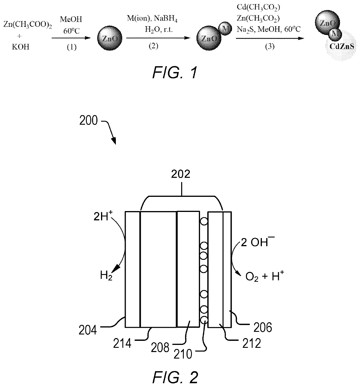
Synthesis of ZnO
[0054]Zn(CH3COO)2.2H2O (2.64 g, 12 mmol) was added to methanol (210 mL) in a 500 mL 3 neck RBF and the temperature was raised to about 60° C. After 10 minutes, methanolic solution of KOH (1.50 g, 26.7 mmol) in 30 mL of water was added drop wise to the reaction solution while stirring and then the stirring was continued for 2 h at 60° C. The color of the solution became turbid at the initial stages and then changed to colorless after 30 min. After 2 h, the solution slowly turned to white color (the particle size also depends on the size of the magnetic bead and rpm of stirring e.g., 600 rpm). Formed ZnO nanoparticles were precipitated out by addition of water and the excess ions were removed by centrifugation. The resulting product was washed with methanol and dried at about 60° C. for 2 hours to give ZnO.
example 2
Synthesis of M1 on ZnO
[0055]Synthesis of Au@ZnO. HAuCl4 (1.97 mg (Au) / mL, 1.7 mL) was added drop-wise to a methanolic solution of ZnO (0.33 g, 4.1 mmol) nanocrystals, followed by 5 mL of NaBH4 (40 mM) aqueous solution. The solution was stirred for 10 min. The solution color became black due to the formation of gold on ZnO nanoparticles. The resulting solution was centrifuged, filtered and dried in air to give Au@ZnO.
[0056]Synthesis of Ag@ZnO. HAgCl4 (1 mg (Ag) / mL, 4 mL) was added drop-wise to a methanolic solution of ZnO (0.33 g, 4.1 mmol) nanocrystals, followed by 5 mL of NaBH4 (40 mM) aqueous solution. The solution was stirred for 10 min. The solution color became black due to the formation of silver on ZnO nanoparticles. The resulting solution was centrifuged, filtered and dried in air to give Ag@ZnO.
[0057]Synthesis of Au / Pd@ZnO. A mixture of HAuCl4 (1.97 mg (Au) / mL, 0.76 mL) and PdCl2 (1.2 mg (Pd) / mL, 1.3 mL) was added drop-wise to a methanolic solution of ZnO (0.33 g, 4.1 mmol)...
example 3
Synthesis of ZnO2@M1@Cd0.8Zn0.2S Compounds
[0059]Zn / M1 (0.2 g, 2.5 mmol) nanoparticles of Example 2 were re-dispersed in 70 mL methanol and the temperature was raised to 60° C. In order to form Cd0.8Zn0.2S layer of the particles, zinc acetate (0.5 mmol) from zinc acetate stock solution (80 mM, 6.25 mL) was added to the dispersion and then the cadmium acetate (2 mmol) from (80 mM, 25 mL) stock solution and sodium sulfide (3 mmol) from (100 mM, 30 mL) methanolic stock solutions were added drop wise simultaneously while stirring the solution. Stirring was continued for 30 min more. Products were separated by centrifugation and washed with H2O / MeOH mixture and dried at 60° C. overnight to give the final product.
[0060]ZnO / Pt / Cd0.8Zn0.2S. ZnO / Pt (0.32 g, 4 mmol) nanoparticles were dispersed in 70 mL methanol and temperature was raised to 60° C. In order to form Cd0.8Zn0.2S layer on the particles, the required amount of zinc acetate (0.2 mmol) from zinc acetate stock solution (80 mM, 2.5 mL...
PUM
| Property | Measurement | Unit |
|---|---|---|
| size | aaaaa | aaaaa |
| size | aaaaa | aaaaa |
| size | aaaaa | aaaaa |
Abstract
Description
Claims
Application Information