Biomass selection and control for continuous flow granular/flocculent activated sludge processes

a technology of granular sludge and sludge, which is applied in the direction of biological sludge treatment, biological water/sewage treatment, oxidation of sludge, etc., can solve the problems of difficult conversion of existing continuously-fed systems to sbr systems for granular sludge selection, inability to address relative, and inability to achieve economic attractiveness, etc., to achieve acceptable and good performance, the effect of assessing the efficiency of the classifier

Active Publication Date: 2020-02-13
OVIVO INC
View PDF3 Cites 15 Cited by
  • Summary
  • Abstract
  • Description
  • Claims
  • Application Information

AI Technical Summary

Benefits of technology

[0045]The granular sludge must be of sufficient size to meet a high SND efficiency so that the outer aerobic fraction of the granule is not a large fraction of the granule biomass and the inner anoxic zone is large enough for the necessary anoxic PAO population and bioreactions. The size of the granular sludge also affects the sludge settling and thickening properties. As the granular size becomes larger the granular sludge settles faster and thickens better and is more capable of SND. However, if the size is too large the biomass is used less efficiently for ammonia and nitrogen removal. Larger granules have less surface area per mass and thus less area for growth of nitrifying bacteria growth. If too large there is a lower nitrification and nitrogen removal efficiency. A proper size range provides both good granule sludge separation and selection and good nitrification and nitrogen removal efficiency.
[0052]The graph results in FIG. 3. are used to assess the efficiency of the classifier test result and show very acceptable and good performance the upflow classifier design and operation. At a 10% granular sludge reject and 65% reject for flocculent sludge, the system SRT for the granules is 6.5 times that of the flocculent sludge. Thus, if the flocculent sludge MLSS concentration is 1,200 mg / L for good clarification the granular sludge MLSS concentration could be as high as 7,800 mg / L. The combined flocculent / granular sludge concentration could then be 9,000 mg / L, which is about 3 times higher than used for conventional activated sludge processes for biological nutrient removal. Higher reject efficiencies lead to higher granular mixed liquor to floc mixed liquor concentrations.

Problems solved by technology

Flocculent sludge can also contain PAOs and can consume soluble biodegradable (bCOD) in the anaerobic contact zone faster than PAO-containing granular sludge because of diffusion limitations for the large and denser granular biomass.
A disadvantage of granular biomass is that the granular structure is not as effective as flocculent biomass in capturing colloidal and suspended particles contained in the wastewater.
Others do not address the need for growth conditions that favor granular biomass growth with preferred types of bacteria over flocculent biomass growth to sustain a high level of granular biomass in the activated sludge process and they also do not address the relative concentrations of granules and flocculent sludge preferred for a combined granular / flocculent sludge process.
Conversion of existing continuously-fed systems to SBR systems for granular sludge selection may be difficult and not economically attractive in most cases in view of the arrangement of the existing tanks and the plant piping and hydraulics.
It is also a very complex system that cannot be easily adapted to existing continuous flow activated sludge systems.
It may also be energy inefficient due to the need to depend on sufficient aeration air lift to accomplish recirculation of flow from the aerobic to anoxic zone.
Its physical arrangement of the zones would not be adaptable to many existing activated sludge systems.
It does not address the ability to provide process conditions that favor the growth of granular biomass over flocculent biomass.
Lack of or poor growth conditions for granular sludge will limit the ability to sustain granular sludge and the reactor mixed liquor solids concentration attainable.
U.S. Pat. No. 9,758,405 does not provide a means for assuring the growth and retention of the PAO granular sludge added from the sidestream batch reactor to the parallel activated sludge reactor.

Method used


Image

  • Biomass selection and control for continuous flow granular/flocculent activated sludge processes
  • Biomass selection and control for continuous flow granular/flocculent activated sludge processes
  • Biomass selection and control for continuous flow granular/flocculent activated sludge processes

Examples


first embodiment

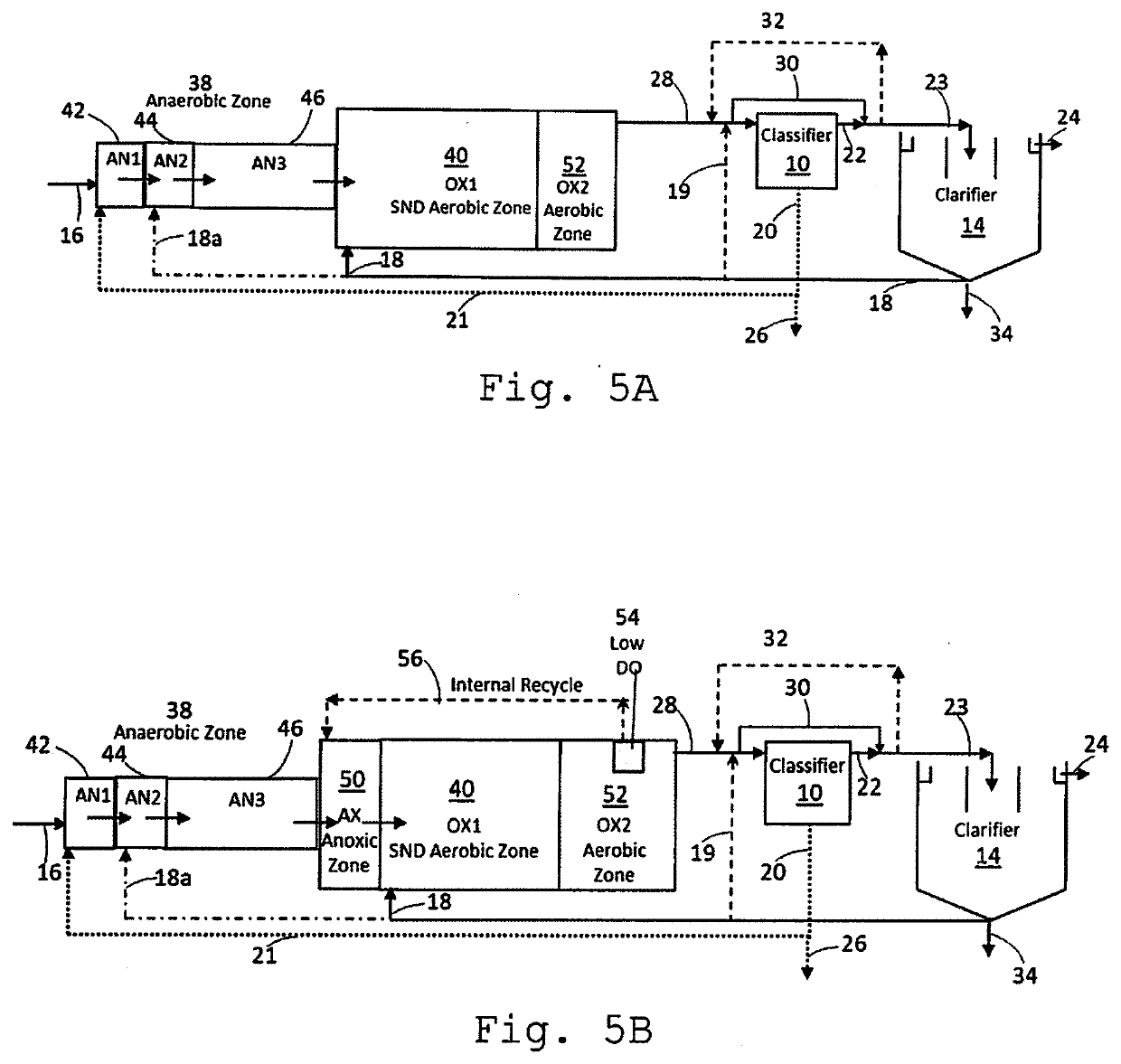
[0077]The first embodiment shown in FIG. 5A is a continuous flow combined granule / flocculent sludge process to grow granules with PAOs and to allow SND to achieve for both biological nitrogen and phosphorus removal. The process has an anaerobic zone 38, an aerobic zone with SND 40, a final aerobic zone at higher DO 52, granular sludge classifier 10, and a secondary clarifier 14.

[0078]Granular sludge is recycled from the classifier line 21 to an anaerobic reactor 42 with a volume that result in a high soluble bCOD loading from the influent flow line 16. The anaerobic zone may have at least 3 stages (3 mixed reactors in series) with the first reactor at a high soluble bCOD loading of greater than 4.8 g soluble bCOD / L-day and less than 30 g soluble bCOD / L-day. The 2nd stage volume 44 is at least as large as the 1st stage and preferably no more than double. The 3rd stage 46 is much larger and can exist as a single tank or be divided into multiple stages. The high soluble bCOD loading as...

embodiment 1

[0084]A modification to Embodiment 1 for wastewater with a low influent soluble bCOD relative to the influent total organic and ammonia nitrogen is shown in FIG. 5B. The modification relies on the degradation of particulate and colloidal solids to provide degradable COD for denitrification. This process contains an anaerobic zone 38 anoxic zone 50, a SND aerobic zone 40, a second aerobic zone 52, a low DO zone 54, a granular sludge classifier 10, and a secondary clarifier 14.

[0085]This process is necessary for applications lacking enough soluble bCOD to enable high removal of nitrogen by SND with PAO granular sludge. Due to the low soluble bCOD:N ratio the amount of stored carbon by PAOs in the anaerobic zone cannot provide enough electron donor to consume a high percentage of the amount of NO3 / NO2 produced in the aerobic zone. An internal recycle flow, line 56, from the low DO zone 54 within the second aerobic zone 52 provides NO3 / NO2 to the unaerated mixed anoxic zone 50 for consu...

embodiment 3

[0098 shown in FIG. 9 is for a continuous flow combined granular / flocculent sludge process for nitrogen removal where phosphorus removal is not needed. No anaerobic zone is used in this case and the granules grown are based on the classifier operation and the soluble bCOD loading to the first stage reactor 54 of the anoxic zone 50. The process contains an anoxic zone 50, an aerobic zone 40, a granular sludge classifier 10 and secondary clarifier 14. The second anoxic reactor 58 may be single stage or divided into two or more stages. The aerobic zone 40 may also be single stage or divided into two or more stages.

[0099]All the features and operational conditions described for the classifier and clarifier and sludge management are applicable and clarifier operation described in Embodiment 1 above with FIG. 5A are included.

[0100]FIGS. 10A through 10D show an energy dissipating inlet (EDI) 110 that can be used in the preferred classifier shown in FIG. 6B. This is sometimes called a rever...


PUM

PropertyMeasurementUnit
concentrationaaaaaaaaaa

Abstract

A continuous flow granular / flocculent sludge wastewater process selects for granule biomass capable of nitrogen and phosphorus removal and controls granule size and concentration of granular and flocculent sludge for optimal nutrient, organic, and solids removal in a smaller footprint. It includes anaerobic, anoxic, and aerobic process zones, a high soluble biodegradable COD loaded first reactor in anaerobic or anoxic zones, a granular sludge classifier with recycle of underflow granular sludge to the first reactor, a secondary clarifier to settle flocculent sludge and particulates and recycle of flocculent sludge from the secondary clarifier underflow to an aerobic process zone. Wasting of sludge from the two separate recycle lines controls the bioprocess flocculent and granular sludge concentrations and SRTs. Bypass around and recycle flow to the classifier to maintain desired flow under various influent flow conditions aid control of granule size. On / off mixer operation of anaerobic and anoxic reactors may be used.

Description

[0001]This application claims benefit of provisional application No. 62 / 718,313, filed Aug. 13, 2018.BACKGROUND OF THE INVENTION[0002]The application involves reactor process configurations and a granular sludge classifier process to control granular sludge size and relative fractions of granular and flocculent activated sludge in a combined continuous flow wastewater treatment system for biological nutrient removal.[0003]The activated sludge process has been used since the early 1900s for the treatment of domestic and industrial wastewater by microorganisms. The basic features of the traditional process are 1) mixing and aeration of the wastewater in a reactor with a flocculent mass containing active microorganisms and influent particulates, 2) a liquid / solids separation step to separate and discharge the treated effluent from the flocculent mass, 3) wasting of excess mass produced from removal of wastewater particulates and biomass growth from the removal of influent substances, 4...

Claims


Application Information

Patent Timeline
Patent Type & Authority Applications(United States)
IPC IPC(8): C02F11/00C02F11/04C02F3/30C02F3/34C02F11/06
CPCC02F3/302C02F3/301C02F11/04C02F11/06C02F3/345C02F2209/04C02F2209/006C02F2209/40C02F11/004C02F2201/007C02F2209/08C02F3/121C02F1/006C02F3/1221C02F2301/043Y02W10/10
Inventor STENSEL, H. DAVIDTRIVEDI, HIRENVORWALLER, JOHNBEAMAN, TYSON
Owner OVIVO INC
Why Eureka
Try Eureka