
Flexible sealing film, flexible sealing member and flexible sealing structure

a sealing film and flexible technology, applied in the direction of sealing/support means, fuel cell details, synthetic resin layered products, etc., can solve the problems of gas or electrolyte seepage, cell current leakage or fracture, other limitations and problems, etc., to achieve high sealing performance, easy processing, and favorable flame retardant performance

Inactive Publication Date: 2020-06-11
MICROCOSM TECH
View PDF0 Cites 0 Cited by
  • Summary
  • Abstract
  • Description
  • Claims
  • Application Information

AI Technical Summary

Benefits of technology

The patent describes a flexible sealing film and a flexible sealing member that has high flame-retardant performance, electric insulation, low gas seepage, chemical resistance, and flexibility. The flexible sealing member can prevent gas or electrolyte liquid seepage, resulting in a durable and reliable flexible sealing structure for batteries. The thermosetting resin layer in the flexible sealing film and membrane electrode assembly has excellent flame retardant performance, electric insulation, low gas permeability, chemical resistance, and mechanical performance. This prevents gas or electrolyte liquid seepage and improves the performance and durability of the battery cell.

Problems solved by technology

In order to increase a power density of the fuel cell, a thickness of each layer structure of the elementary cell needs to be reduced, but the reduction of the thickness causes other limitations and problems.
For example, easy cracking of a rubber material of a sealing member of the membrane electrode assembly after long time use at high temperature, slippage or separation of the gas diffusion electrode and the electrolyte membrane from the sealing member, insufficient toughness or mechanical pressure resistance of the sealing member and the like all may cause gas or electrolyte seepage, or even cause problems of cell current leakage or fracture, etc., which leads to reduced cell performance and durability.
Therefore, how to improve the sealing performance of the fuel cell is one of problems expected to be solved by those skilled in the art at present.

Method used

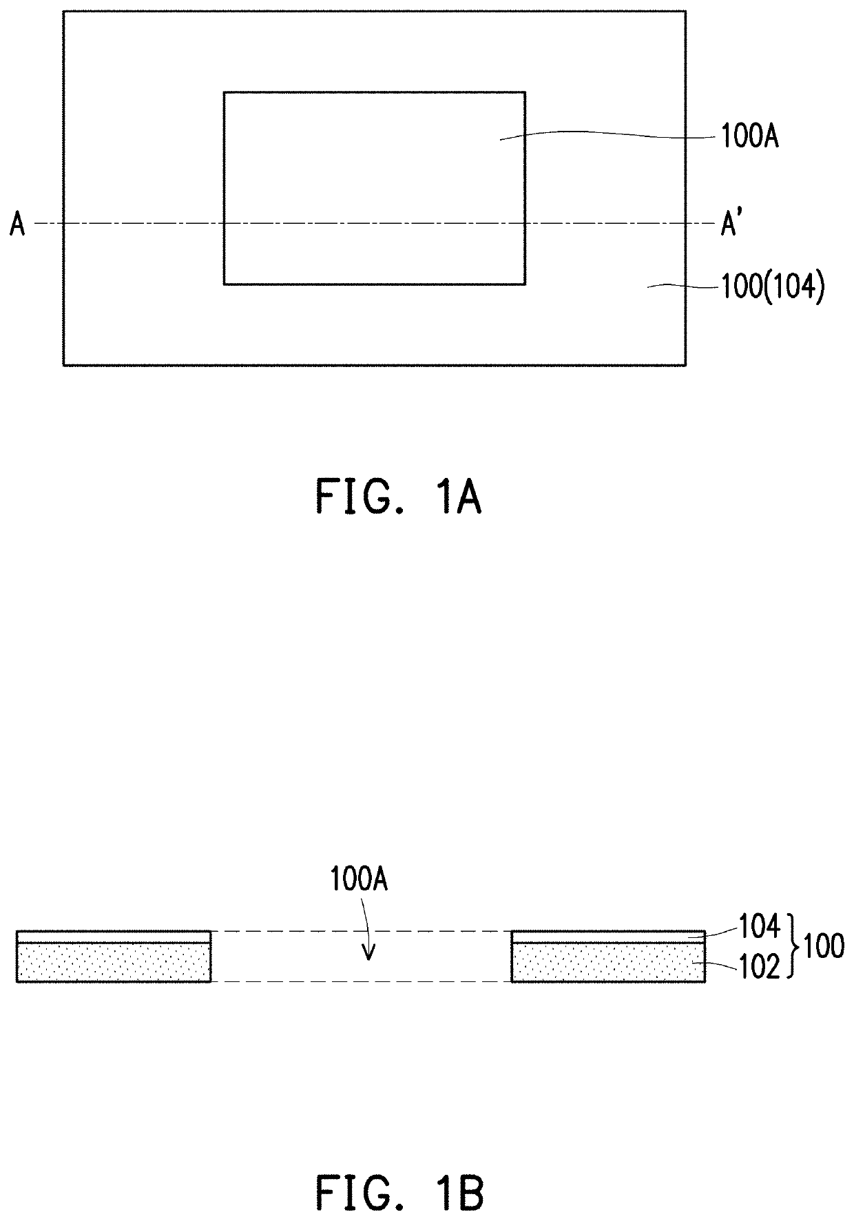

Image

  • Flexible sealing film, flexible sealing member and flexible sealing structure
  • Flexible sealing film, flexible sealing member and flexible sealing structure
  • Flexible sealing film, flexible sealing member and flexible sealing structure

Examples


experiment 1

[0071]Hereafter, the characteristics of the thermosetting resin layer in the flexible sealing film of the invention are illustrated in detail with reference to Table 1 and Table 2.

[0072]The thermosetting resin layers in Example 1 to Example 4 and Comparative examples will be prepared according to the main agent composition and proportion in Table 1 below:

Example NumberCompositionExampleExampleExampleExampleComparative(parts by weight)1234ExampleEpoxy resin (Note 1)100100100100100Phosphorous flame retardant5010075750(Note 2)Silicon dioxide55280(Note 3)ToughingLiquid-state NBR2402400agent(Note 4)Solid-sate NBR1201200(Note 5)NBR derivative0360036(Note 6)PhosphineTPP (Note 7)0.20.20.20.20.2compoundIonSb2O3·2H2O1.51.51.501.5exchangerBi(OH)0.7(NO3)0.31.51.51.501.5SolventMethyl ethyl187237204100215ketoneN-propyl alcohol88888FinishedViscosity (cps)300300300300300productSolid content (%)5050505050pH value6.87.76.56.67.3Note 1:manufactured by Changchun Chemical, trade name: EB 501Note 2:manuf...

experiment 2

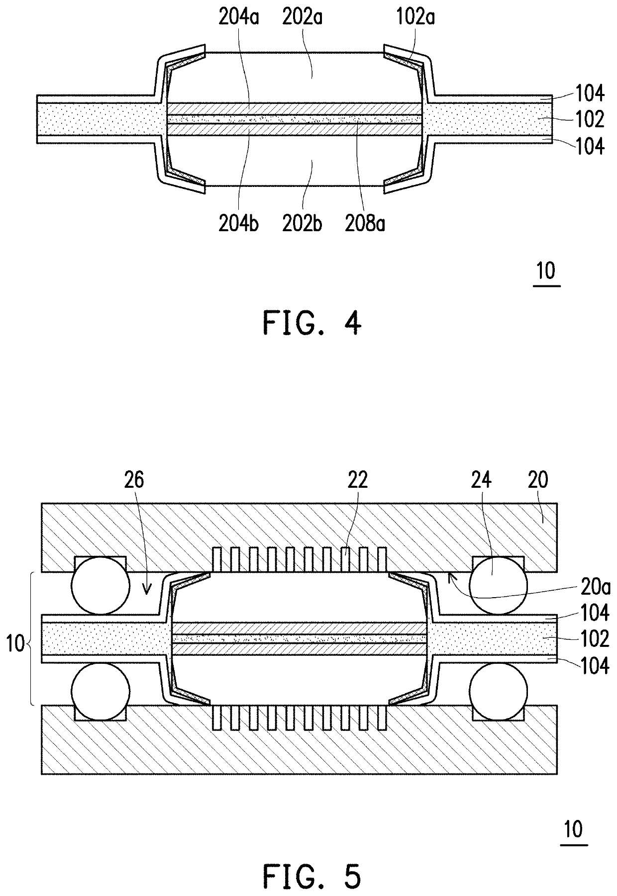
[0084]FIG. 5 is a schematic partial cross-sectional view of a flexible sealing structure after being assembled with a runner plate according to an embodiment of the invention. FIG. 6 is an appearance photo of a flexible sealing structure according to the embodiment of the invention. FIG. 7 is a partial appearance photo of FIG. 6. FIG. 8 is a partial appearance photo of a finished product of a flexible sealing structure according to the embodiment of the invention.

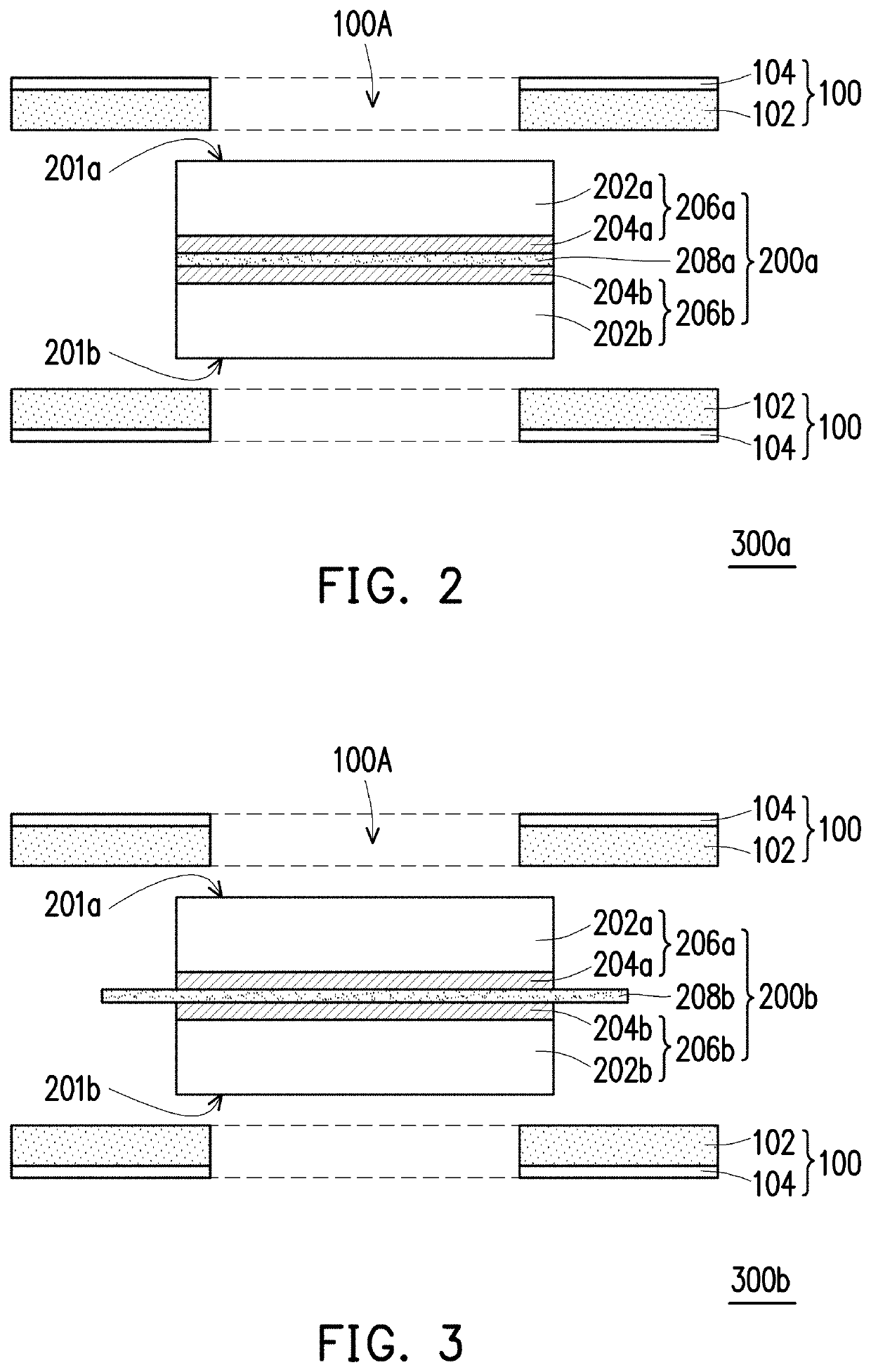
[0085]Hereafter, characteristics of the flexible sealing structure of the invention are illustrated in detail with reference to Table 3 and FIG. 2 to FIG. 8.

example 1

[0086]In the present embodiment, a membrane electrode assembly uses an even side surface assembly mode (as shown in FIG. 2). An electrolyte membrane layer in the membrane electrode assembly is a polybenzimidazole (PBI) electrolyte membrane. A preparation mode is immersing the PBI electrolyte membrane into phosphoric acid for 1 hour at 60° C. to enable the total immersion amount to be approximately between 180 wt % and 220 wt % to obtain a phosphorylated PBI electrolyte membrane. A gas diffusion electrode in the membrane electrode assembly uses carbon cloth as a cathode gas diffusion layer and an anode gas diffusion layer, which has a thickness of 370 μm. Next, for an electrode catalyst layer in the gas diffusion electrode, a commercial Pt / C catalyst slurry is coated onto the cathode gas diffusion layer and the anode gas diffusion layer, and is dried at 160° C. to form an electrode catalyst layer on each of the cathode gas diffusion layer and the anode gas diffusion layer, the cathod...


PUM

PropertyMeasurementUnit
particle diameteraaaaaaaaaa
thicknessaaaaaaaaaa

Abstract

The invention provides a flexible sealing film. The flexible sealing film includes a polymer layer and a thermosetting resin layer. The thermosetting layer is arranged on a surface of the polymer layer, and includes: (a) 100 parts by weight of epoxy resin, (b) 50 parts by weight to 100 parts by weight of a phosphorous flame retardant, (c) 20 parts by weight to 50 parts by weight of a toughening agent, (d) 0.1 parts by weight to 2.0 parts by weight of a phosphine compound, (e) 2 parts by weight to 12 parts by weight of silicon dioxide, and (f) 1 part by weight to 10 parts by weight of an ion exchanger. The invention further provides a flexible sealing film and a flexible sealing structure.

Description

CROSS-REFERENCE TO RELATED APPLICATION[0001]This application claims the priority benefit of Taiwan application serial no. 107143958, filed on Dec. 6, 2018. The entirety of the above-mentioned patent application is hereby incorporated by reference herein and made a part of this specification.BACKGROUND OF THE INVENTION1. Field of the Invention[0002]The invention relates to a sealing film, a sealing member, and a sealing structure, and in particular, to a flexible sealing film, a flexible sealing member, and a flexible sealing structure.2. Description of Related Art[0003]A fuel cell is a device for generating current through reaction between hydrogen fuel gas and oxidizing agent gas by electrochemical stack-up. An electrolyte membrane as a core element in the fuel cell can be configured to provide high proton or ion conduction, block electrons and block gas fuel passing at two ends. A sealing member in the fuel cell is configured to enhance mechanical performance of an elementary cell...

Claims


Application Information

Patent Timeline
Patent Type & Authority Applications(United States)
IPC IPC(8): B32B27/08C08K5/00C08K5/52C08K5/50C08K3/36C08K9/06C08K3/22H01M8/0284B32B27/18B32B27/38H01M8/0286H01M8/1004
CPCC08K3/36C08K5/52C08K2201/003H01M8/1004C08K5/0066B32B2307/31C08K3/2279C08K9/06B32B27/38H01M8/0284H01M8/0286B32B2305/72B32B27/08C08K5/50B32B27/18H01M8/0273B32B7/12B32B27/281B32B27/285B32B27/286B32B27/288B32B27/302B32B27/304B32B27/32B32B27/322B32B27/325B32B27/34B32B27/36B32B2250/02B32B2250/24B32B2307/3065B32B2307/7242B32B2307/732B32B2581/00C08K5/523Y02E60/50C08L63/00
Inventor YEH, CHUN-TINGJHENG, SIH-CI
Owner MICROCOSM TECH
Learn More