Additive manufacturing method and device for ceramic and composite thereof

a technology of additive manufacturing and ceramic composites, which is applied in the direction of ceramic materials production, heat inorganic powder coating, metallic material coating process, etc., can solve the problems of low forming efficiency and energy/material utilization, high equipment investment and operating cost, and difficult to achieve full density

Pending Publication Date: 2020-12-24
HUAZHONG UNIV OF SCI & TECH
View PDF10 Cites 10 Cited by
  • Summary
  • Abstract
  • Description
  • Claims
  • Application Information

AI Technical Summary

Benefits of technology

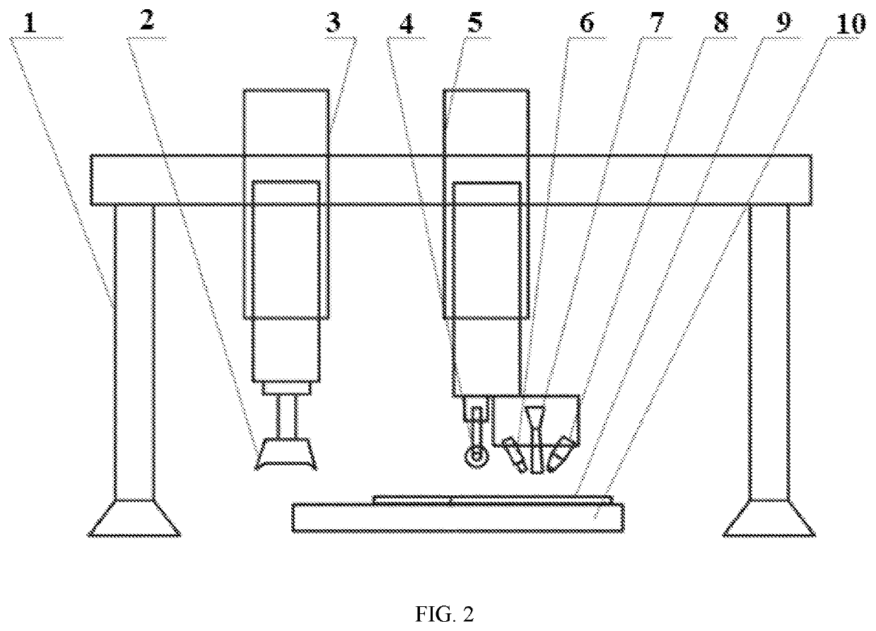
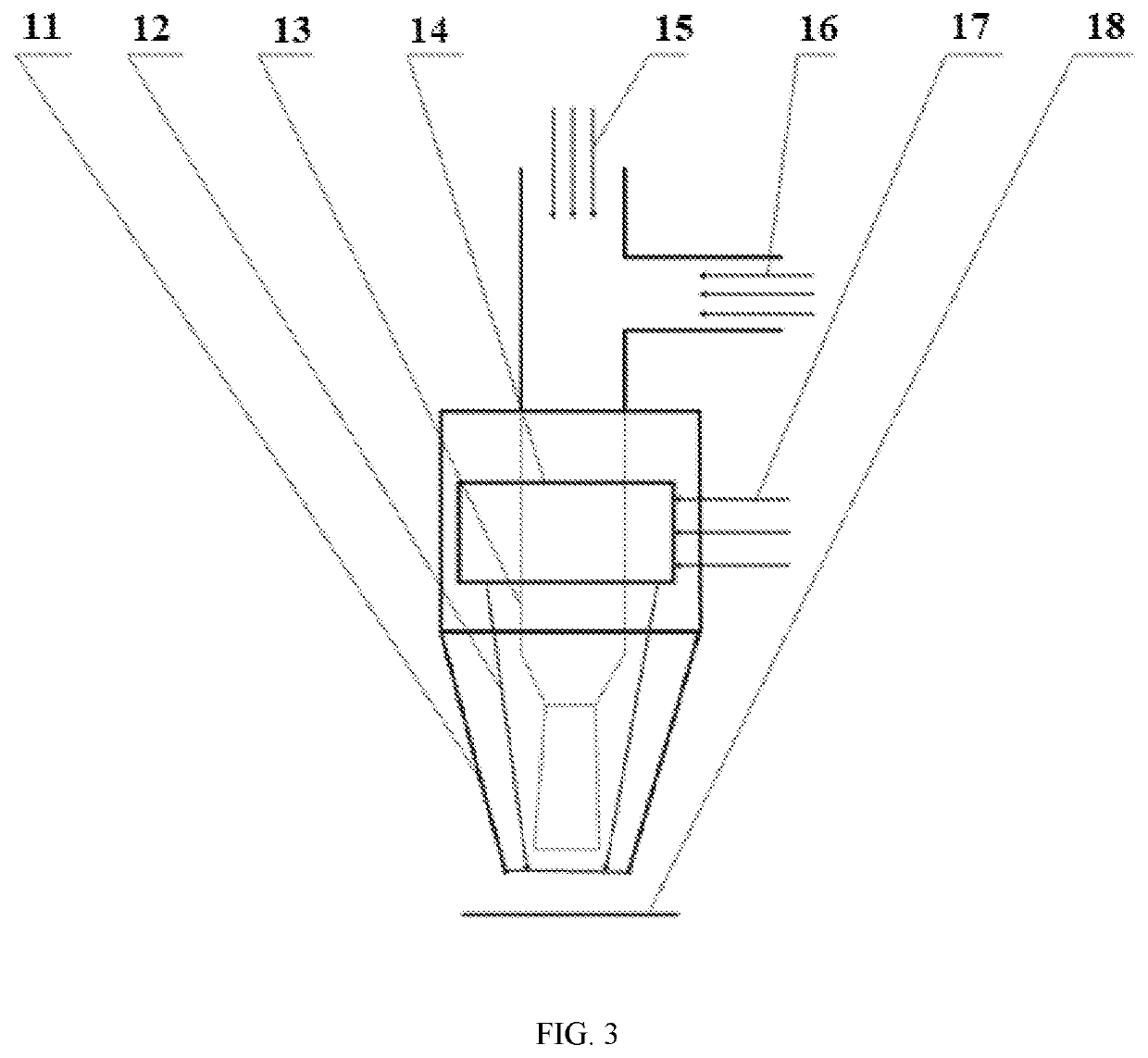
[0039]When the coating substrate is preheated and the printed uppermost slice layer is heated, a temperature sensor 6 may be configured to monitor the temperature of the heating area in real time. The parameters (power, pulse width and frequency) of the laser beam or electron beam are subjected to real-time closed-loop feedback adjustment according to an optimal deposition temperature of different sprayed materials so that the preheated substrate and the printed uppermost slice layer maintain the optimal deposition temperature. Meanwhile, the heating of the laser beam and other heat sources reduces the critical speed and critical temperature required for the deposition of high-melting-point materials such as ceramics and their alloys, and reduces the requirements for the working gas (that is, N2 may be used instead of He to reduce the AM cost). The disclosure softens the surface of a deposited layer while another layer is deposited to enhance the plasticity of the deposited layer, stabilize the deposition process, and improve the forming quality. The sprayed particles are selected from high-melting-point materials such as ceramics, cermets and ceramic composites, and argon or nitrogen may be used as the working gas during the deposition process.
[0024]The heating module is configured to preheat a substrate and heat a spray area to a temperature until the spraying deposition of all slice layers is completed. The temperature is in a range of the melting point of a sprayed powder minus 200° C. to the melting point of the sprayed powder.
[0024]The heating module is configured to preheat a substrate and heat a spray area to a temperature until the spraying deposition of all slice layers is completed. The temperature is in a range of the melting point of a sprayed powder minus 200° C. to the melting point of the sprayed powder.
[0039]When the coating substrate is preheated and the printed uppermost slice layer is heated, a temperature sensor 6 may be configured to monitor the temperature of the heating area in real time. The parameters (power, pulse width and frequency) of the laser beam or electron beam are subjected to real-time closed-loop feedback adjustment according to an optimal deposition temperature of different sprayed materials so that the preheated substrate and the printed uppermost slice layer maintain the optimal deposition temperature. Meanwhile, the heating of the laser beam and other heat sources reduces the critical speed and critical temperature required for the deposition of high-melting-point materials such as ceramics and their alloys, and reduces the requirements for the working gas (that is, N2 may be used instead of He to reduce the AM cost). The disclosure softens the surface of a deposited layer while another layer is deposited to enhance the plasticity of the deposited layer, stabilize the deposition process, and improve the forming quality. The sprayed particles are selected from high-melting-point materials such as ceramics, cermets and ceramic composites, and argon or nitrogen may be used as the working gas during the deposition process.
[0039]When the coating substrate is preheated and the printed uppermost slice layer is heated, a temperature sensor 6 may be configured to monitor the temperature of the heating area in real time. The parameters (power, pulse width and frequency) of the laser beam or electron beam are subjected to real-time closed-loop feedback adjustment according to an optimal deposition temperature of different sprayed materials so that the preheated substrate and the printed uppermost slice layer maintain the optimal deposition temperature. Meanwhile, the heating of the laser beam and other heat sources reduces the critical speed and critical temperature required for the deposition of high-melting-point materials such as ceramics and their alloys, and reduces the requirements for the working gas (that is, N2 may be used instead of He to reduce the AM cost). The disclosure softens the surface of a deposited layer while another layer is deposited to enhance the plasticity of the deposited layer, stabilize the deposition process, and improve the forming quality. The sprayed particles are selected from high-melting-point materials such as ceramics, cermets and ceramic composites, and argon or nitrogen may be used as the working gas during the deposition process.
[0039]When the coating substrate is preheated and the printed uppermost slice layer is heated, a temperature sensor 6 may be configured to monitor the temperature of the heating area in real time. The parameters (power, pulse width and frequency) of the laser beam or electron beam are subjected to real-time closed-loop feedback adjustment according to an optimal deposition temperature of different sprayed materials so that the preheated substrate and the printed uppermost slice layer maintain the optimal deposition temperature. Meanwhile, the heating of the laser beam and other heat sources reduces the critical speed and critical temperature required for the deposition of high-melting-point materials such as ceramics and their alloys, and reduces the requirements for the working gas (that is, N2 may be used instead of He to reduce the AM cost). The disclosure softens the surface of a deposited layer while another layer is deposited to enhance the plasticity of the deposited layer, stabilize the deposition process, and improve the forming quality. The sprayed particles are selected from high-melting-point materials such as ceramics, cermets and ceramic composites, and argon or nitrogen may be used as the working gas during the deposition process.
[0039]When the coating substrate is preheated and the printed uppermost slice layer is heated, a temperature sensor 6 may be configured to monitor the temperature of the heating area in real time. The parameters (power, pulse width and frequency) of the laser beam or electron beam are subjected to real-time closed-loop feedback adjustment according to an optimal deposition temperature of different sprayed materials so that the preheated substrate and the printed uppermost slice layer maintain the optimal deposition temperature. Meanwhile, the heating of the laser beam and other heat sources reduces the critical speed and critical temperature required for the deposition of high-melting-point materials such as ceramics and their alloys, and reduces the requirements for the working gas (that is, N2 may be used instead of He to reduce the AM cost). The disclosure softens the surface of a deposited layer while another layer is deposited to enhance the plasticity of the deposited layer, stabilize the deposition process, and improve the forming quality. The sprayed particles are selected from high-melting-point materials such as ceramics, cermets and ceramic composites, and argon or nitrogen may be used as the working gas during the deposition process.

Problems solved by technology

However, its forming efficiency and energy / material utilization are low, the equipment investment and operating cost are high, and it is not easy to achieve full density.
However, the process conditions are strict, and the entire forming process needs to be performed in a vacuum, which results in limited forming dimensions and high equipment investment and operating costs.
In addition, because it uses the same layer-by-layer powder spreading method as SLS, it is difficult to form with functionally graded materials (FGM).
However, due to the larger diameter of the plasma plume, the size and surface accuracies of this method are not as high as these two methods.
However, the direct forming process will increase the surface hardness of the difficult-to-machine parts due to rapid solidification, resulting in difficult machining.
This has become a bottleneck for the low-cost, short-flow manufacturing of high-performance difficult-to-machine parts.
However, due to the lack of support, during the forming process of complex-shaped parts with overhangs, the molten material may fall and flow under the action of gravity, making it difficult to deposit.
However, for complex-shaped parts with large inclination angles on the sides, especially those with lateral overhanging angles, the flow and fall caused by gravity during the deposition process cannot be avoided, making lateral growth difficult.
However, it is difficult for these heat sources to form complex, fine, thin-walled parts, and their forming precision and thin-walledness are not as good as the LDT (Almeida PMS, Williams S: Innovative Process Model of Ti-6AI-4V Additive Layer Manufacturing Using Cold Metal Transfer (CMT) [C], Proceedings of the 21st Annual International Solid Freeform Fabrication Symposium, Austin, Tex., USA, 2010: 25-26).
However, TS also has many defects.
First, the spraying process needs to melt the metal particles, resulting in a high spraying temperature, causing thermal stress inside the substrate and thermal deformation on the surface of the substrate.
Second, because manual operation is impossible except for flame spraying (FS), the operation is dangerous.
In addition, the traditional TS process has poor spraying effect since the spraying area and thickness are difficult to control, and the device is not portable.
However, they are difficult to obtain coatings with large thicknesses and densities, and are thus difficult to meet the requirements of high-end aerospace equipment such as aero-engines for the surface modification of parts.
Featuring rapid heating, rapid solidification, and free growth, the existing moldless AM methods are difficult to avoid cracks and porosity during the AM process, resulting in that the microstructure, performance, and stability of parts is not satisfactory.
The above problems have become the key technical problems that restrict the further development of the direct energy deposition (DED) technology and the implementation of industrial application.

Method used


Image

  • Additive manufacturing method and device for ceramic and composite thereof
  • Additive manufacturing method and device for ceramic and composite thereof
  • Additive manufacturing method and device for ceramic and composite thereof

Examples


example 1

[0047]According to the performance requirements of a superalloy part, a superalloy powder may be used for high-speed CS forming.

[0048]A forming substrate is heated to 900° C. to 1,000° C. by heating outside a spray chamber or heating inside the spray chamber with a heating coil. A high-speed CS gun is moved on the forming substrate to deposit the metal based on a digital additive forming path derived from a 3D CAD model of the part.

[0049]In the forming process, a heat source fixed beside the high-speed CS gun simultaneously heated a spray area to a temperature of 1,200° C. to 1,300° C., and a micro-roller fixed behind the high-speed CS gun moved with the gun to perform continuous cold rolling. In this way, high-speed CS forming and pressure forming (PF) are carried out simultaneously. If size and surface accuracies are not satisfactory, surface finishing is performed layer by layer or by several layers by a milling device in the synchronous forming process. Or, grinding and polishin...

example 2

[0051]According to the performance requirements of an aluminum alloy part, an aluminum alloy powder may be used for high-speed CS forming.

[0052]A forming substrate is heated to 600° C. to 800° C. by heating outside a spray chamber or heating inside the spray chamber with a heating coil. A high-speed CS gun is moved on the forming substrate to deposit the metal based on a digital additive forming path derived from a 3D CAD model of the part.

[0053]In the forming process, a heat source fixed beside the high-speed CS gun simultaneously heated a spray area to a temperature of 900° C. to 1,100° C., and a micro-roller fixed behind the high-speed CS gun moved with the gun to perform continuous cold rolling. In this way, high-speed CS forming and PF are carried out simultaneously. If size and surface accuracies are not satisfactory, surface finishing is performed layer by layer or by several layers by a milling device in the synchronous forming process. Or, grinding and polishing are perform...

example 3

[0055]According to the performance requirements of a ceramic part, a zirconia ceramic powder may be used for high-speed CS forming.

[0056]A forming substrate is heated to 900° C. to 1,100° C. by heating outside a spray chamber or heating inside the spray chamber with a heating coil. A high-speed CS gun is moved on the forming substrate to deposit the metal based on a digital additive forming path derived from a 3D CAD model of the part.

[0057]In the forming process, a first heating unit fixed beside the high-speed CS gun simultaneously heated a spray area to a temperature of 1,000° C. to 1,200° C., and a micro-roller fixed behind the high-speed CS gun moved with the gun to perform continuous cold rolling. In this way, high-speed CS forming and PF are carried out simultaneously. If size and surface accuracies are not satisfactory, surface finishing is performed layer by layer or by several layers by a milling device in the synchronous forming process. Or, grinding and polishing are per...


PUM

PropertyMeasurementUnit
melting pointaaaaaaaaaa
temperatureaaaaaaaaaa

Abstract

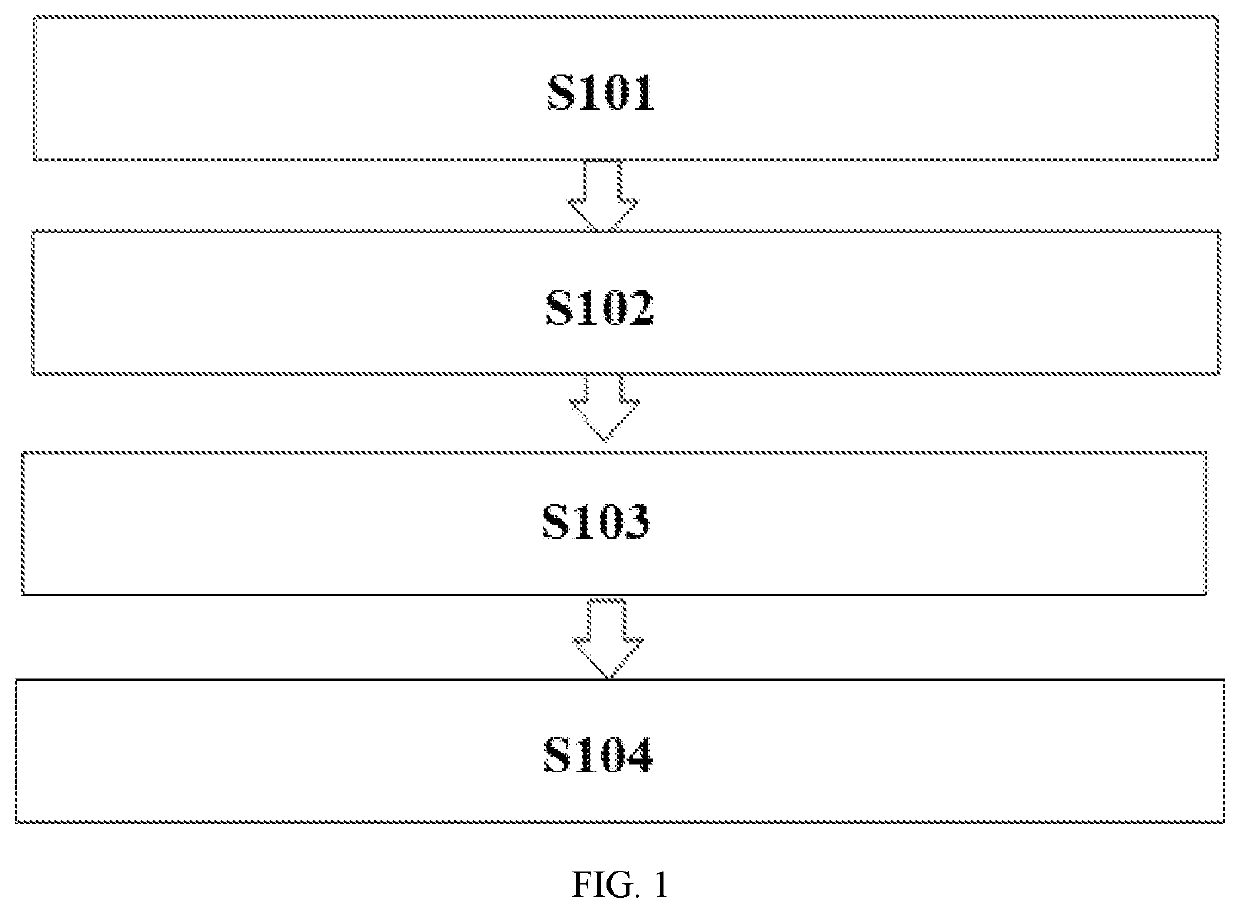
Additive manufacturing (AM) methods and devices for high-melting-point materials are disclosed. In an embodiment, an additive manufacturing method includes the following steps. (S1) Slicing a three-dimensional computer-aided design model of a workpiece into multiple layers according to shape, thickness, and size accuracy requirements, and obtaining data of the multiple layers. (S2) Planning a forming path according to the data of the multiple layers and generating computer numerical control (CNC) codes for forming the multiple layers. (S3) Obtaining a formed part by preheating a substrate, performing a layer-by-layer spraying deposition by a cold spraying method, and heating a spray area to a temperature until the spraying deposition of all sliced layers is completed. (S4) Subjecting the formed part to a surface modification treatment by a laser shock peening method.

Description

CROSS REFERENCE TO RELATED APPLICATIONS[0001]This application claims priority to Chinese application number 201910546152.4 filed on Jun. 24, 2019, the disclosure of which is incorporated by reference herein in its entirety.FIELD OF THE DISCLOSURE[0002]The disclosure relates generally to additive manufacturing (AM) of materials with high melting points. More specifically, the disclosure relates to AM methods and devices for ceramics and ceramic composites.BACKGROUND[0003]Additive manufacturing (AM) processes of high-melting-point materials mainly include laser deposition technology (LDT), electron-beam freeform fabrication (EBF3) and plasma arc deposition (PAD).[0004]The LDT uses a high-power laser to melt the metal powder sent to the substrate layer by layer and quickly solidify the deposit to form a near-net-shape part. The method has high forming precision and higher workpiece density than that of the selective laser sintering (SLS) process. However, its forming efficiency and ene...

Claims


Application Information

Patent Timeline
Patent Type & Authority Applications(United States)
IPC IPC(8): B28B11/08B33Y10/00B33Y30/00B28B1/00B22F3/00C22F1/04
CPCB22F3/008B33Y10/00B28B11/089B28B1/001B28B11/0872B33Y30/00C22F1/04B28B1/24B22F2003/1051B22F10/00B22F10/36B22F12/53B22F12/17B22F10/66B22F10/25B22F12/90B22F10/50B22F2999/00B22F3/18Y02P10/25B33Y40/20B22F2003/242B22F2003/247B22F3/168C23C24/04C04B2235/6026C23C24/08C23C24/082C23C24/087C04B35/486C04B2235/665Y02P40/60B22F2202/11B22F2203/11B22F2203/03
Inventor ZHANG, HAI'OUHU, XIAOQIWANG, GUILANYANG, CHENG
Owner HUAZHONG UNIV OF SCI & TECH
Why Eureka
Try Eureka