
Positive Electrode Precursor

a precursor and electrode technology, applied in the field of positive electrode precursors, can solve the problems of limited use, inferior durability and output characteristics of electric double layer capacitors, and achieve the effects of short time, high capacitance, and promoting decomposition of alkali metal compounds

Inactive Publication Date: 2021-07-01
ASAHI KASEI KK
View PDF0 Cites 0 Cited by
  • Summary
  • Abstract
  • Description
  • Claims
  • Application Information

AI Technical Summary

Benefits of technology

The present invention provides a positive electrode precursor that can quickly pre-doping the negative electrode by promoting decomposition of the alkali metal compound and has a high capacitance. Additionally, the invention offers a method for producing a nonaqueous hybrid capacitor that can pre-doping lithium ions to the negative electrode without using metal lithium and has low gas generation during storage at high temperatures and good charging and discharging cycle characteristics under high load.

Problems solved by technology

Durability (cycle characteristics and storage characteristics at high temperatures) thereof is inferior to that of the electric double layer capacitor.
Therefore, it is limited to be used in a narrower range of discharging depth of 0 to 100% to hold practical durability.
However, each of these existing storage elements has its merits and demerits.
On the other hand, in the case where an oxide or a carbon material is used as the electrode, and charging and discharging are carried out by Faraday reaction, the energy density is increased (for example, a density of ten times obtainable by non-Faraday reaction using the activated carbon), however, problems occur in the durability and the output characteristics.
However, it has a problem in output characteristics and durability in spite of a high energy density (ten times at the positive electrode x ten times at the negative electrode=100).
Furthermore, depth of discharging should be restricted to satisfy high durability which is required in a hybrid electric car, and 10 to 50% of the energy can only be used for the lithium ion secondary battery.
According to this method, however, doping of lithium ions becomes unstable in the negative electrode.
Therefore, the pre-doping method using the metal lithium foil had a problem of not exhibiting the high output of the element.
However, there is a problem that the lithium oxalate which has low oxidation potential causes gas generation by gradual decomposition thereof, and remains in the electrolytic solution or the negative electrode during a long period of storage.
These methods, however, have not considered at all pre-doping to the negative electrode in the nonaqueous hybrid capacitor, and there has remained much room for enhancing efficiency of pre-doping and exhibiting a higher capacitance of the nonaqueous hybrid capacitor.

Method used

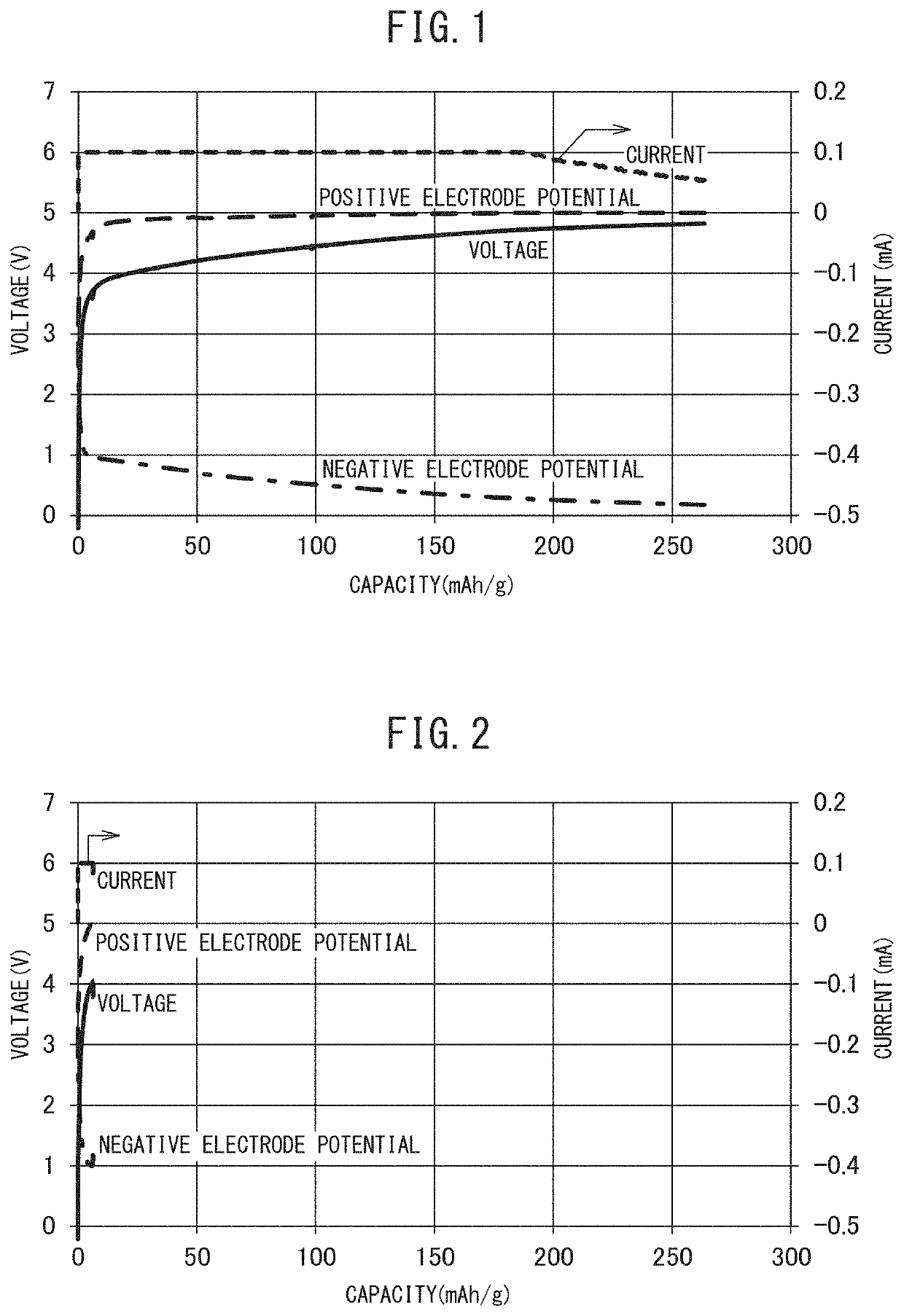
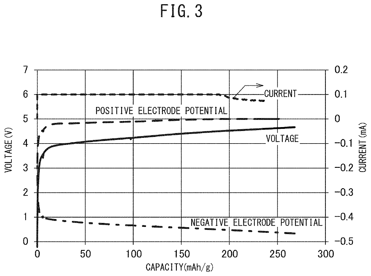

Image

  • Positive Electrode Precursor
  • Positive Electrode Precursor

Examples


example 1

Preparation of Positive Electrode Active Material

preparation example 1a

[0241]A carbide was obtained by carbonization treatment of a crushed coconut shell carbide in a compact-type carbonization furnace at 500° C. for 3 hours under a nitrogen atmosphere. The resulting carbide was put inside an activation furnace where steam which was heated in a preheating furnace was introduced to the activation furnace in a warm state at a rate of 1 kg / h, and activated by increasing a temperature up to 900° C. over a period of 8 hours. The carbide after activation was taken out, and cooled it down under a nitrogen atmosphere, from which an activated carbon was obtained. The resulting activated carbon was washed in a passing water bath for 10 hours. After the activated carbon was dried for 10 hours in an electric drying machine at 115° C., it was crushed for 1 hour using a ball mill, and then activated carbon 1 was obtained.

[0242]The average particle diameter of this activated carbon 1 was 4.2 μm measured by using a laser diffraction-type particle size distribution mea...

preparation example 2a

[0243]A carbide having an average particle diameter of 7 μm was obtained by carrying out carbonization of a phenol resin in a furnace at 600° C. for 2 hours under a nitrogen atmosphere, crushing it using a ball mill, followed by classification of the carbide. Activation was carried out by mixing the carbide and KOH in the weight ratio of 1:5, and heating the mixture at 800° C. for 1 hour in the furnace under a nitrogen atmosphere. Then, activated carbon 2 was obtained by washing it under stirring for 1 hour in diluted hydrochloric acid whose concentration was adjusted to that of 2 mol / L, washing with distilled water under boiling in which pH is held in a range of pH 5 to 6, and then carrying out drying.

[0244]The average particle diameter of activated carbon 2 was 7.0 μm measured by using a laser diffraction-type particle size distribution measurement apparatus (SALD-2000), manufactured by Shimadzu Corp. The fine pore distribution thereof was measured using a fine pore distribution m...


PUM

PropertyMeasurementUnit
particle diameteraaaaaaaaaa
voltageaaaaaaaaaa

Abstract

This positive electrode precursor includes: a positive electrode active material containing a carbon material and an alkali metal compound, wherein 5≤A≤35, when A (g / m2) is a weight of the alkali metal compound in the positive electrode active material layer at one surface of the positive electrode precursor, 10≤B≤100 as well as 0.20≤A / B≤1.00, when B (g / m2) is a weight of the positive electrode active material in the positive electrode active material layer, and 1≤C≤20, when C (m2 / cm2) is a specific surface area per unit area as measured by the BET method at one surface of the positive electrode precursor.

Description

RELATED APPLICATION DATA[0001]This application is a divisional application of U.S. application Ser. No. 15 / 761,085 filed on Mar. 16, 2018, which is a § 371 National Stage Application of PCT International Application No. PCT / JP2017 / 002006 filed Jan. 20, 2017, which claims priority to Japanese Patent Application Nos. 2016-010895 filed Jan. 22, 2016; 2016-155698 filed Aug. 8, 2016; and 2016-155837 filed Aug. 8, 2016, the entire contents of each of these applications are incorporated herein by reference.TECHNICAL FIELD[0002]The present invention relates to a positive electrode precursor.BACKGROUND ART[0003]In recent years, a power smoothing system of wind power generation or a midnight power storage system, a household dispersive power storage system based on solar power generation technologies, a power storage system for an electric car, and etc. have been received attention from the viewpoint of effective utilization of energy aiming at conservation of global environment and resource ...

Claims


Application Information

Patent Timeline
Patent Type & Authority Applications(United States)
IPC IPC(8): H01G11/06H01G11/24H01G11/64H01M4/1393H01M10/052H01M10/0567H01M10/0585H01G11/84H01G11/34H01G11/26H01G11/86
CPCH01G11/06H01G11/24H01G11/64H01M4/1393H01M10/052H01G11/46H01M10/0585H01G11/84H01G11/34H01G11/26H01G11/86H01M10/0567Y02E60/10Y02E60/13Y02T10/70Y02P70/50H01G11/04H01G11/32
Inventor UMETSU, KAZUTERUOKADA, NOBUHIROKUSUZAKA, KEITA
Owner ASAHI KASEI KK
Learn More