
Bioabsorbable stent

Pending Publication Date: 2021-11-18
JAPAN MEDICAL DEVICE TECH
View PDF0 Cites 0 Cited by
  • Summary
  • Abstract
  • Description
  • Claims
  • Application Information

AI Technical Summary

Benefits of technology

The patent is about a way to make a stent made of magnesium alloy that is safe and can be absorbed by the body. The method involves using a coating made of magnesium fluoride and a safe, carbon-based layer made of diamond-like carbon to prevent corrosion and improve the stent's ability to follow the body's contours.

Problems solved by technology

However, although coronary-arteries stent surgery gains popularity nowadays, there have been still many cases to cause complications at a certain period of postoperative time.
On the other hand, the bare metal stent made of a bioabsorbable magnesium alloy body has a problem that mechanical strength is spoiled immediately during expansion in an aqueous solution because of acceleration of decomposition (corrosion) throughout the surface where water molecules are in contact.
Accordingly, such a bioabsorbable magnesium stent has difficulty in practical application.
Considering the requirement to maintain sufficient blood vessel bearing power (radial force) for 1 to 6 months after stent implant, the bioabsorbable magnesium has by no means suitable characteristics.
The method includes forming a magnesium fluoride layer on the surface of the magnesium alloy body, and then further forming chemical conversion film layers of aluminum oxide (Al2O3) and a poly(aluminum ethylene glycol) polymer (alucone) on the magnesium fluoride layer because single magnesium fluoride layer is not sufficiently capable of having the corrosion of the material delayed.

Method used


Image

  • Bioabsorbable stent
  • Bioabsorbable stent

Examples


example 1

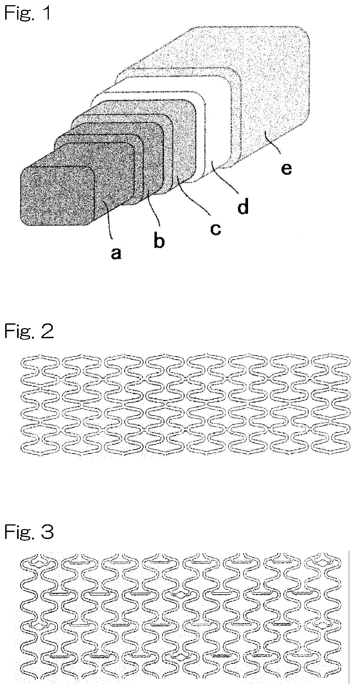
[0118]A core structure comprising the above-described stent scaffold formed from the magnesium alloy obtained in the Production Example 1 was immersed in a 27 M hydrofluoric-acid aqueous solution (2 mL) and reciprocally moved at a rate of 100 rpm. Then, the stent was taken out after 24 hours, and subjected to ultrasonic cleaning sufficiently with water and acetone followed by drying the core structure for 24 hours at 60° C. under vacuum to prepare a core structure on which a first corrosion resistant layer (thickness: 1 μm) was formed. A diamond-like carbon coat layer having a thickness of 50 nm was formed on this structure so as to form a second corrosion resistant layer. Onto a surface of thus-obtained structure, a first cover layer containing 400 μg of a first polymer PCL was spray-coated, and then a second cover layer containing 150 μg of a second polymer PDLLA and 100 μg of sirolimus was spray-coated so as to obtain a stent sample shown in FIG. 1.

example 2

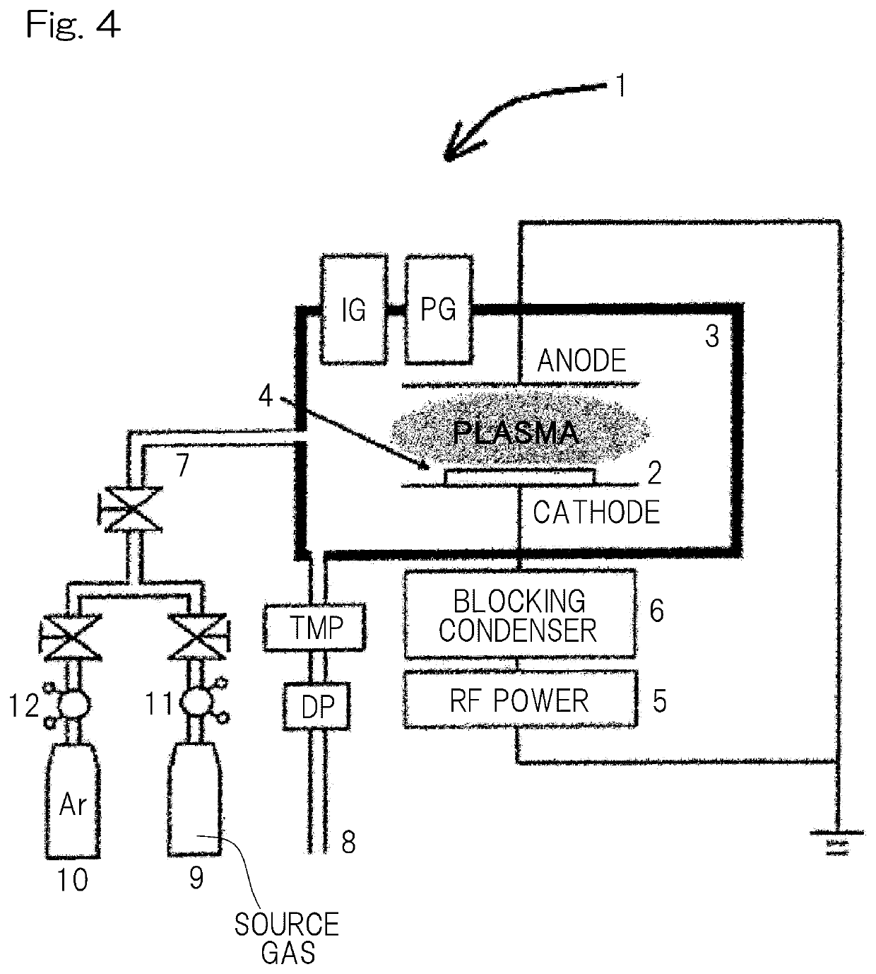
[0129]A core structure comprising the above-described stent scaffold formed from the magnesium alloy obtained in the Production Example 1 was immersed in a 27 M hydrofluoric-acid aqueous solution (2 mL) and reciprocally moved at a rate of 100 rpm. Then, the stent was taken out after 24 hours, and subjected to ultrasonic cleaning sufficiently with water and acetone followed by drying the core structure for 24 hours at 60° C. under vacuum to prepare a core structure on which a first corrosion resistant layer (thickness: 1 μm) was formed. This structure was placed in the plasma CVD apparatus shown in FIG. 4, and then tetramethylsilane was introduced as a source gas using the apparatus shown in FIG. 4 to form a silicon-containing diamond-like carbon coat layer as a second corrosion resistant layer having a thickness of 50 nm on this structure. Onto a surface of thus-obtained structure, a first cover layer containing 400 μg of a first polymer PCL was spray-coated, and then a second cover...


PUM

PropertyMeasurementUnit
Fractionaaaaaaaaaa
Fractionaaaaaaaaaa
Fractionaaaaaaaaaa

Abstract

Provided are a magnesium alloy stent with improved corrosion resistance, and a method for producing same. The bioabsorbable stent including a core structure of a magnesium alloy, the stent is composed of: a first anticorrosive layer containing magnesium fluoride as a main component formed on the core structure, and a second anticorrosive layer coated with a diamond-like carbon on the first anticorrosive layer.

Description

CROSS REFERENCE TO THE RELATED APPLICATION[0001]This application is continuation application, under 35 U.S.C. § 111(a), of international application No. PCT / JP2020 / 003050, filed Jan. 28, 2020, which claims priority to Japanese Patent Application No. 2019-014434, filed Jan. 30, 2019, Japanese Patent Application No. 2019-062873, filed Mar. 28, 2019, and Japanese Patent Application No. 2020-001519 filed Jan. 8, 2020, the entire disclosures of all of which are herein incorporated by reference as a part of this application.[0002]The present invention relates to a bioabsorbable stent that is implanted in a stenosis part or an occlusion part, especially in the coronary arteries, in lumen of living body so as to keep the inserted part open, and to be gradually degraded in the living body.BACKGROUND ART[0003]The ischemic heart diseases (myocardial infarction, angina, etc.) caused by stenosis and occlusion of the coronary arteries are critical diseases which disturb supply of the blood (nutri...

Claims


Application Information

Patent Timeline
IPC IPC(8): A61L31/14A61L31/08A61L31/02A61L31/10A61L31/16
CPCA61L31/148A61L31/088A61L31/022A61L31/10A61L2420/08A61L31/084A61L2300/416A61L2420/02A61L31/16A61F2/915A61F2210/0004A61F2002/91575C08L67/04
Inventor YAMASHITA, SHUZOSASAKI, MAKOTOWADA, AKIRA
Owner JAPAN MEDICAL DEVICE TECH
Learn More